Introduction
Test engineers face a critical challenge: capturing transient events with microsecond precision while minimizing false triggers and missed signals. When a mechanical impact occurs, a voltage threshold is crossed, or an encoder pulse fires, software-based polling introduces variable latency—in the millisecond range—that makes deterministic measurement impossible. Hardware triggering solves this by starting, pausing, or referencing acquisition based on an external electrical signal detected directly by the hardware, bypassing the host computer entirely.
This guide is written for test engineers, manufacturing engineers, and system integrators working with DAQ systems in industrial, automotive, aerospace, and laboratory environments. Removing the host CPU from the timing loop lets you capture time-sensitive events—vibration spikes, fault conditions, synchronized multi-channel data—with repeatable precision that software polling cannot match. As NI's DAQmx documentation confirms, hardware triggers bypass OS jitter entirely, while software triggers remain subject to Windows and Linux scheduler variability.
Key Takeaways
- Hardware triggering synchronizes data collection to a real-world electrical event, eliminating host-computer latency
- Primary trigger signal types are digital (TTL edge/level) and analog (voltage threshold/slope)
- Not all DAQ devices support both signal types — confirm compatibility before selecting hardware
- Trigger modes include start, reference (pre/post-trigger), pause, and retriggerable tasks
- Key reliability factors: signal integrity, device compatibility, hysteresis, and buffer configuration
- Slow measurements can use software triggering without measurable latency impact — hardware triggering is not always required
What Is Hardware Triggering in DAQ Systems?
Hardware triggering lets a DAQ device's onboard circuitry monitor an external signal and start acquisition the instant a specified condition is met. No host CPU polling required — the trigger detection logic lives on the DAQ board itself, running independently of your application software.
Software triggering, by contrast, relies on your application detecting a condition — say, a voltage reading crossing a threshold — and then issuing a start command. That handoff introduces variable latency, typically around 1 ms on Windows systems, which rules it out for deterministic, time-stamped measurement of fast events such as:
- Impact testing, where the strike event defines time zero
- Encoder synchronization requiring sub-millisecond alignment
- Fault detection where the exact onset moment matters
With hardware triggering, you capture signal data precisely aligned to an external event — a mechanical impact, encoder pulse, or threshold crossing. That alignment means you analyze only the relevant waveform window, conserving memory and improving data quality. Your pre-trigger buffer also records what happened in the moments just before a fault, which is often the most diagnostic data you have.
Types of Hardware Triggers in DAQ Systems
Digital Triggers
A digital trigger monitors a TTL or logic-level signal on a dedicated PFI (Programmable Function Interface) or digital input pin. The DAQ hardware watches for a rising edge, falling edge, or static high/low level condition. Digital triggers are supported across nearly all major DAQ device series—M, X, C, S, E, and B series—and are the default choice when your trigger source is a clean digital signal from a PLC, encoder, or function generator.
Why digital triggers are preferred: They're immune to analog noise, require no threshold calibration, and work with any device that has PFI routing to the timing engine.
Analog Triggers
Onboard Analog Trigger Circuitry (ATC) continuously compares the incoming analog voltage against a user-defined level and slope, generating an internal trigger when the condition is met. Analog triggering requires dedicated hardware and is only available on certain device series:
- X Series: 6351, 6353, 6361, 6363 (most models)
- M Series: 6250, 6251, 6280, 6281 (select models)
- S Series: 6110, 6115, 6120, 6132 (most models)
- E Series: 6030E, 6040E, 6052E, 6070E (select models)
- C Series: Module-dependent (e.g., 9205 supports analog triggering; 9201 does not)
- B Series: 6008, 6009, 6010 (no analog trigger support)
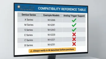
Always verify support in NI's trigger compatibility tables before specifying hardware for your application.
Start Triggers
The most common trigger mode. The DAQ task waits in an armed state and begins sampling the moment the trigger condition fires. The trigger marks the beginning of the useful data record, making it ideal for capturing events that start at a known electrical signal.
Reference Triggers (Pre-Trigger/Post-Trigger)
The DAQ system continuously fills a circular pre-trigger buffer before the trigger event fires, then captures a defined number of post-trigger samples after the crossing. This is essential when you need to see what happened immediately before a fault.
Common applications include vibration analysis, impact testing, and end-of-line quality testing — anywhere the fault signature begins before the trigger threshold is reached.
Pause Triggers and Retriggerable Tasks
Two additional modes handle non-continuous and repetitive acquisition scenarios:
- Pause triggers suspend sampling while the trigger signal holds a defined state, gating acquisition to active machine cycles only.
- Retriggerable tasks restart the same acquisition sequence each time a new trigger fires — no software re-arming needed between events, useful when capturing dozens or hundreds of consecutive events without software re-arming delays between each.
How Hardware Triggering Works
Conceptual Flow
Hardware triggering follows a fixed pipeline—each stage hands off to the next with no CPU involvement:
- Configure the DAQ task: channels, sample rate, buffer size, trigger source, and trigger type
- Arm the task — the hardware enters a waiting state, monitoring the trigger line continuously
- Detect the trigger condition via onboard circuitry
- Initiate the A/D conversion clock immediately upon detection
- Stream data into the onboard FIFO, then transfer it to the host buffer via DMA
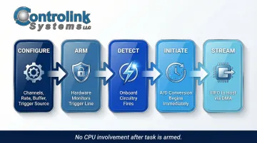
The entire sequence runs autonomously once the task is armed.
Setting Up the Trigger Source and Task Parameters
You select a physical PFI pin (for digital triggers) or an analog input channel (for analog triggers) as the trigger source. Then you define:
- Active edge (rising/falling) or threshold level
- Slope (rising/falling for analog triggers)
- Hysteresis value (voltage window to prevent re-triggering on noise)
- Pre-trigger sample count and total sample count
This configuration is handled through the NI-DAQmx driver API and is abstracted by software environments like LabVIEW or Python. Controlink Systems has been an NI Partner since 2000 and can validate these settings against your physical test requirements before deployment.
Arming and Waiting for the Trigger Event
Once the task is committed and started, the DAQ hardware enters a waiting state: its trigger detection circuitry is active, but its sample clock is paused. No data is streamed to the host until the trigger fires. This is what removes CPU polling latency from the timing equation—your measurement timing is now determined by hardware, not OS scheduler jitter.
Trigger Detection and Data Acquisition
At the moment the trigger condition is met, the onboard trigger circuitry asserts an internal start signal to the sample clock. A/D conversions begin immediately (or for reference triggers, the pre-trigger buffer is frozen and post-trigger sampling continues). Data is written to the hardware FIFO (First-In-First-Out buffer) before being transferred to the host driver buffer via Direct Memory Access (DMA).
Key Factors That Affect Hardware Triggering Performance
Signal Integrity on the Trigger Line
Noise, ground loops, or long cable runs on the trigger signal can cause false triggers or missed events. NI's field wiring guide recommends:
- Use shielded, twisted-pair cables (such as NI's -EPM series)
- Connect shield to ground at the source end only (prevents ground loops)
- Add hysteresis on analog triggers to prevent re-triggering on noise
- Locate signal conditioning close to the DAQ device
- Ensure trigger source impedance is less than 1 kΩ for APFI lines
Device Compatibility and Trigger Feature Support
Not every DAQ device supports every trigger type. Specifically, analog triggering requires dedicated ATC hardware absent from many lower-cost boards (such as the B Series 6008/6009 and C Series modules like 9201). Verify trigger capability in the device datasheet or NI's trigger support documentation before system design—not after purchase.
Trigger Timing Parameters
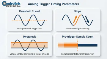
Incorrectly configured analog trigger levels or insufficient hysteresis bands cause spurious triggers. Key parameters:
- Threshold/Level: Voltage at which trigger fires
- Slope: Rising or falling edge
- Hysteresis: Voltage window that prevents re-trigger on noise (NI DAQmx documentation recommends always configuring hysteresis for analog triggers)
- Trigger delay: Samples to skip after trigger before recording
- Pre-trigger sample count: Must be sized relative to signal behavior and sample rate
Buffer Sizing and Sample Rate
If the DAQ buffer is too small for the post-trigger sample count at the configured rate, a buffer overflow (Error -200361) or incomplete capture results.
Beyond trigger configuration, buffer sizing determines whether captured data is complete and usable.
Practical rule: The total acquisition window (pre-trigger samples + post-trigger samples ÷ sample rate) should fully capture the signal event of interest, with margin to spare.
For example, capturing a 50 ms transient at 10 kS/s requires at least 500 samples — but allocate 750–1,000 samples to account for timing variability.
Common Issues and When Hardware Triggering May Not Be Appropriate
Common Misconceptions and Mistakes
Many engineers assume hardware triggering is automatically better in all scenarios, or that a correctly armed task will always catch the first event. Critical errors include:
- Task not armed before trigger event occurs: If your physical trigger fires before you execute the DAQmx Start Task function, the event is missed entirely. NI's retriggerable task documentation emphasizes pre-allocating resources and arming tasks well in advance.
- Connecting trigger signal to non-PFI general digital I/O pin: Only terminals routed directly to the timing engine (PFI, RTSI, PXI_STAR) can initiate hardware-timed actions. A standard digital I/O line lacks this routing, resulting in no response.
- Insufficient hysteresis on noisy analog signals: Causes rapid re-triggering and false acquisitions.
When Hardware Triggering Is Unnecessary
Software triggering is sufficient when the event timescale is seconds or longer. These scenarios introduce negligible timing error:
- Thermal monitoring or steady-state chemical readings
- Low-speed structural tests where millisecond precision isn't required
Device capability is a separate limiter. If your hardware doesn't support the trigger type you need—for example, analog triggering on a B Series 6008—complex workarounds rarely justify the effort. Software triggering or a device upgrade is the more practical path.
Signals That Hardware Triggering Is Used by Default Rather Than by Need
Two patterns indicate you may be over-engineering the trigger setup:
- Routing a software-generated pulse through a digital output back into a PFI pin just to mimic a hardware trigger
- No pre-trigger data requirement and timing tolerance of ±10 ms or more
In either case, software triggering is simpler and produces the same result. If precision isn't the requirement, don't design for it.
Frequently Asked Questions
What is the difference between NI DAQ and NI-DAQmx?
NI DAQ refers to National Instruments' family of data acquisition hardware devices (the physical boards and modules). NI-DAQmx is the driver software and API that communicates with and controls those devices—handling task configuration, triggering, timing, and data transfer between the hardware and your host application.
What devices are supported by NI-DAQmx?
NI-DAQmx supports M Series, X Series, C Series, S Series, E Series, B Series, mioDAQ USB, and PXI multifunction I/O modules, among others. For the full list, visit NI's hardware compatibility page.
How do I configure NI DAQ?
NI DAQ devices are configured using NI MAX (Measurement & Automation Explorer) to assign device names and verify hardware, then programmed via NI-DAQmx APIs in environments like LabVIEW, Python, or C to define channels, sample rates, and trigger settings.
Is a DAQ an ADC?
A DAQ system contains an ADC (analog-to-digital converter) as a core component but is not simply an ADC. It also includes signal conditioning, timing and triggering circuitry, digital I/O, a hardware clock, and a driver interface that together make it a complete data acquisition system.
Is a DAQ a microcontroller?
No. A DAQ device is a dedicated measurement instrument designed to acquire, condition, and transfer sensor data to a host PC. Unlike a microcontroller, it runs no user code onboard. It relies entirely on a connected computer and driver software to define its behavior.
What is the best way to simulate NI-DAQmx hardware so I can start programming without the hardware connected?
NI MAX allows you to create simulated NI-DAQmx devices that mimic real hardware for task configuration and code development without physical equipment. Be aware that simulated devices do not simulate triggering—triggers return immediately—and cannot validate physical wiring or hardware-dependent behavior.
Need help configuring hardware triggering for your test system? Controlink Systems LLC has been an NI Partner Network member since 2000, delivering DAQ hardware and software integration for manufacturing and test applications. Contact our team at (800) 838-3479 or email support@controlinksystems.com to discuss your requirements.