Introduction
Factory operators face a persistent challenge: flow processes running on mismatched or manually adjusted systems create inconsistent throughput, unplanned downtime, and scrap accumulation . Fortune Global 500 companies lose almost $1.4 trillion annually through unplanned downtime — 11% of total revenues. In automotive manufacturing alone, that figure hits $2.3 million per hour.
PLC integration addresses these losses directly — connecting sensors, actuators, HMIs, and control logic into a single automated flow control system that responds to real-world conditions without waiting for a human to intervene. This article explains how that integration works, what it takes to implement it, and where it delivers the most measurable impact on factory throughput.
Key Takeaways
- PLCs monitor inputs and adjust flow in milliseconds, executing control logic in 50 µs to 10 ms
- Common integration stack: Modbus for sensor polling, Profinet/EtherCAT for drive control, OPC-UA for SCADA connectivity
- Automated PLC flow control reduces scrap by 0.5% or more and cuts downtime by 30–50% through predictive maintenance
- Before deployment, map your architecture, match I/O modules, and validate exception-handling logic
What Is PLC Integration for Automated Flow Control?
PLC integration means networking a programmable logic controller with sensors, output devices, and higher-level software to manage continuous or sequential flow of materials, fluids, or processes across a factory floor.
The PLC isn't a standalone controller. It exchanges data with upstream and downstream equipment, HMIs, and sometimes SQL databases or ERP systems—creating coordinated flow across the entire facility.
Discrete vs. Process Flow Control in Manufacturing
PLCs handle two types of control. Discrete control involves on/off decisions like a press cycle or a gate opening. Continuous or process flow control regulates speed, pressure, valve position, or conveyor pacing—requiring analog I/O and feedback loops, not just digital switching.
Modern PLCs execute complex analog control (PID loops) at 10-20 ms scan rates, making them suitable for high-speed flow applications. In contrast, Distributed Control Systems (DCS) traditionally used for process control run at 100-500 ms scan rates.
Automated flow control applies in:
- Conveyor pacing and synchronization across assembly lines
- Fluid or gas flow regulation through proportional valves
- Assembly line throughput management
- Feed rate control in machining or stamping environments
That coordination depends entirely on the communication layer. Controlink Systems—with over 25 years in factory automation—implements integrations across Modbus, Profinet, EtherCAT, and serial protocols, ensuring PLCs communicate reliably with the full device ecosystem on the shop floor.
How PLCs Manage Flow Control in Real Time
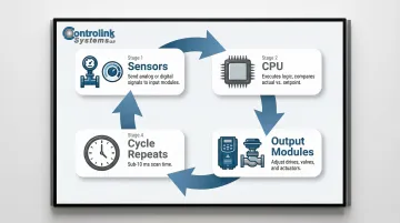
PLCs use a closed-loop control model: sensors send signals to input modules, the CPU compares actual vs. setpoint values, and output modules adjust actuators or drives—all within milliseconds.
The closed-loop cycle:
- Sensors (flow meters, pressure transducers, encoders, proximity sensors) send analog or digital signals to PLC input modules
- CPU executes programmed logic to compare actual vs. setpoint values
- Output modules adjust actuators, variable frequency drives (VFDs), or valve controllers
- Cycle repeats in sub-10 ms scan times
Common Flow Control Scenarios on the Factory Floor
Scenario 1: Conveyor synchronization
A PLC paces belt speed to match machine cycle time and prevent part jams. Encoders track belt position, and the PLC adjusts VFD speed to maintain spacing between parts.
Scenario 2: Fluid dispensing line
The PLC reads a flow meter and adjusts a proportional valve to hit a precise fill volume. A PID loop continuously corrects valve position based on flow rate feedback.
Scenario 3: Multi-station assembly line
The PLC gates part movement between stations based on cycle completion signals. Parts advance only when the downstream station signals "ready," preventing collisions and buffer overflow.
Scenario 4: Fault and exception handling
When a sensor reads out of range or a downstream station signals "not ready," the PLC triggers alarms, pauses flow, and logs fault data—rather than shutting down the entire line. This localized response keeps the rest of production running while the fault is isolated and addressed.
Why PLC Speed Matters for Flow Accuracy
The scenarios above only work because PLCs respond faster than any human or mechanical system can. Human visual reaction time averages 331 milliseconds, and traditional mechanical relays take 8-10 ms to switch. Modern PLCs execute logic in microseconds. Beckhoff TwinCAT, for example, runs base cycle times as low as 50 µs.
At those speeds, a 50 ms delay isn't minor — it's enough to cause overfill, underfill, part jams, or conveyor pile-ups. That response margin is what makes precise flow regulation possible.
Key Integration Components: Sensors, Protocols, and HMIs
Sensor and I/O Layer
Flow control relies on physical data sources:
- Flow meters measure liquid or gas volume per unit time
- Pressure transducers monitor hydraulic or pneumatic pressure
- Encoders track rotational position or speed
- Temperature sensors ensure process conditions stay within spec
- Photoelectric sensors detect part presence or absence
Analog input modules translate these signals into PLC-readable values. Matching sensor signal type (4-20 mA, 0-10 V, discrete) to the correct I/O module is critical. The ISA-50.1-1982 standard defines the 4-20 mA current loop, and the NAMUR NE43 recommendation standardizes fault detection: signals ≤ 3.6 mA or ≥ 21.0 mA indicate hardware faults.
Communication Protocols That Connect the Flow Control System
Industrial communication protocols link the PLC to other devices on the network:
| Protocol | Timing Characteristics | Use Case |
|---|---|---|
| Modbus RTU/TCP | 253-byte PDU; client/server polling | Analog sensor data, legacy device integration |
| Profinet IRT | Cycle times down to 31.25 µs with 1 µs jitter | Real-time deterministic control of drives and actuators |
| EtherCAT | ≤ 100 µs cycle times, ≤ 1 µs jitter | High-speed synchronized motion; 200 analog I/O (16 bit) in 50 µs |
Profinet IRT eliminates variable data delays by reserving bandwidth for cyclic data packets, protecting time-sensitive data from TCP/IP traffic. A clock master synchronizes all local clock pulse generators to a common clock, ensuring maximum cycle time deviation of 1 µs.
Controlink Systems implements integrations across all three protocols, bridging PLC hardware with sensors, drives, and actuators across mixed-vendor shop floor environments.
HMI Layer
Operator interfaces display real-time flow data, allow setpoint changes, and surface alarms. The PLC-to-HMI data exchange requires precise configuration — latency or data mismatch in flow-critical applications can cause incorrect operator readings or missed alarm conditions.
Common PLC-to-HMI communication options include:
- OPC-UA — vendor-neutral data exchange with built-in security and semantic modeling
- Ethernet/IP (CIP) — uses a producer-consumer model; native to Rockwell and many mid-market PLCs
- Modbus TCP — straightforward polling; widely supported by legacy HMI panels
ODVA and the OPC Foundation are jointly developing a CIP Companion Specification for OPC UA. Once finalized, OPC UA applications will read data directly from CIP devices without requiring CIP-native translation — simplifying integration across mixed-protocol HMI deployments.
Database and SCADA Integration
Beyond the operator display layer, PLCs push flow data — flow rates, cycle counts, fault logs — to SQL databases or SCADA platforms for supervisory monitoring, trend analysis, and compliance documentation. This persistent data record is what enables predictive maintenance: historical fault patterns identify failing components before they cause downtime, and process trend data supports ongoing optimization of setpoints and throughput targets.
Benefits of PLC-Driven Flow Control in Manufacturing
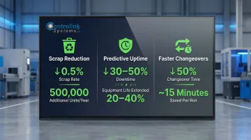
Three measurable gains stand out when manufacturers move from manual to PLC-driven flow control:
- Scrap reduction: Setpoints are held precisely and responded to instantly, eliminating operator-dependent variability. One plastics manufacturer cut scrap by 0.5%—translating to 500,000 additional bottles per year.
- Predictive uptime: PLCs continuously log process variables, catching drift early (a pump slowing before it fails, for example). PLC-enabled predictive maintenance can reduce unplanned downtime by 30–50% and extend equipment life by 20–40%—significant when unplanned stoppages cost $260,000 per hour in general manufacturing and up to $2.3 million per hour in automotive.
- Faster changeovers: Stored flow control recipes let operators switch product runs from an HMI without rewiring or manual recalibration. Rockwell Automation's Integrated Architecture helped one manufacturer cut format changeover time by 50%—roughly 15 minutes per run—directly improving OEE.
Implementing PLC Integration for Flow Control: Practical Steps
Define the system architecture first: Before selecting hardware, map the full flow path. Identify every sensor point, actuator, control loop, communication node, and higher-level system (HMI, SCADA, database) that needs to be part of the integration. A poorly scoped architecture is the leading cause of integration failures and rework.
Select hardware for the environment:
- Match PLC I/O module types to sensor signals (4-20 mA vs. 0-10 V vs. discrete)
- Choose communication modules that support required protocols (Modbus, Profinet, EtherCAT)
- Account for electrical noise and temperature range in the installation environment—factors that directly affect flow measurement accuracy
Test with real process conditions before go-live: Simulate fault scenarios—sensor loss, out-of-range values, communication interruptions—to verify that the PLC's exception-handling logic responds correctly and flow is safely controlled or halted, not left in an undefined state.
One frequently overlooked detail: Rockwell Automation recommends using periodic tasks rather than continuous tasks when tuning PIDs. Running a PID block in a continuous task—which varies from 15–30 ms—against a fixed 500 ms update time introduces significant errors in Integral and Derivative math.
When integration spans multiple protocols and legacy equipment, the design and commissioning phases grow considerably more complex. Controlink Systems LLC has handled exactly these scenarios—bridging Modbus, Profinet, EtherCAT, and serial protocols within a single control architecture—since 1998.
Frequently Asked Questions
What is the role of a PLC in automated flow control?
A PLC acts as the central controller that reads flow-related sensor inputs, executes programmed logic to compare actual versus target values, and sends corrective output signals to actuators or drives. This all happens in real time, within 10-20 ms scan cycles.
Which communication protocols are most commonly used for PLC-based flow control integration?
Modbus is widely used for analog sensors and simple polling, Profinet and EtherCAT serve real-time drive and actuator control with sub-millisecond determinism, and serial/CAN interfaces remain common for legacy devices. Protocol choice depends on required response speed and device compatibility.
How does a PLC integrate with SCADA and HMI systems in a factory flow control setup?
PLCs pass real-time process data to HMIs for operator visibility and setpoint control, while SCADA systems aggregate data from multiple PLCs for supervisory monitoring and logging—typically via OPC-UA, Ethernet/IP, or Modbus TCP.
What types of sensors are used with PLCs for factory flow control?
Common sensor types include flow meters, pressure transducers, encoders, and photoelectric sensors. The sensor signal type (analog 4-20 mA vs. digital) must match the PLC's input module for accurate data capture, following industry wiring standards for signal compatibility.
What are the most common challenges when integrating PLCs into existing factory flow control systems?
Protocol mismatches between legacy devices and modern PLCs, improper I/O module selection for sensor signal types, and insufficient exception-handling logic that leaves processes in undefined states during faults are the most common integration challenges.
How do integrated PLC flow control systems help reduce scrap and downtime?
PLCs enforce precise setpoints automatically, detect process drift before it causes out-of-spec output, and log data that supports scheduled maintenance over reactive shutdowns. In practice, this reduces downtime by 30-50% and scrap rates by 0.5% or more.