Introduction
Every CNC machine runs on instructions — and those instructions live in a CNC file. Whether you're cutting an automotive engine block or a medical implant, that file tells the machine exactly what tool to use, how fast to spin it, and the precise path it should follow through the material.
Yet beginners face practical friction at every stage: multiple file formats (DXF, STL, G-code), a multi-step creation workflow (CAD → CAM → machine), and the real risk of running an outdated or incorrect file on a machine. That last mistake alone can result in scrapped parts, damaged tooling, or worse—a machine crash that halts production for hours.
This guide covers the full lifecycle of a CNC file — from creation to the machine:
- What CNC files are and the formats they come in (DXF, STL, G-code)
- How they're created through the CAD → CAM → machine workflow
- How files get sent to a machine reliably
- How to manage files in a production environment without running outdated programs
Key Takeaways
- CNC files are digital instruction sets—typically G-code—that tell a CNC machine how to move and cut
- The creation process follows a defined sequence: design in CAD → generate toolpaths in CAM → export G-code → send to machine
- File format choice depends on your machine type and the specific operation being performed
- Common beginner mistakes include skipping toolpath verification, using wrong units, or working from an outdated file version
- Reliable file delivery and version control matter as much as getting the file right
What Are CNC Files and When Are They Used?
Understanding the Three Layers of CNC Files
"CNC file" is an umbrella term covering several file types used at different stages of the manufacturing workflow. The three layers work in sequence, and each serves a different purpose:
- CAD files define the geometric design of the part (e.g., STEP, IGES, SolidWorks)
- CAM files contain toolpath data and cutting strategies (e.g., Mastercam project files)
- G-code files are the final machine instruction files that controllers execute (e.g., .nc, .tap, .cnc)
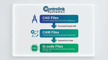
You cannot send a CAD file directly to a CNC controller: it must first be processed through CAM software to generate G-code. The same applies to 3D mesh files like STL, which use triangulated meshes that lack parametric data and true curves — making them unsuitable for tight-tolerance milling without CAM conversion first.
When CNC Files Are Appropriate
CNC files are used across a wide range of operational contexts:
- One-off prototype runs where a single part is machined to validate a design
- High-volume repeat production where the same program runs hundreds or thousands of times
- Multi-machine environments where identical parts are produced on different machines simultaneously
- Scenarios requiring consistency where multiple operators must produce the same part reliably
That last point matters more than it might seem. The global CNC machine market is projected to reach $105.7 billion by 2031, with automotive (32.4% market share) and medical device manufacturing (7.15% CAGR) leading growth. In both sectors, a single bad file revision reaching the shop floor can mean scrapped parts, missed deadlines, and real money lost.
What You Need Before Creating a CNC File
Before you can create a CNC file, you need the right tools and knowledge in place. Skipping these prerequisites leads to errors that aren't always obvious until a part is scrapped or a tool breaks.
Core Software Requirements
- CAD software (e.g., Fusion 360, SolidWorks, Inkscape for 2D) — produces the geometric design that becomes the basis of the file; without accurate geometry, every step after it builds on that mistake
- CAM software (e.g., Fusion 360 CAM, Mastercam, Vectric) — translates the design into machine-specific toolpaths and exports G-code
- Machine-specific post-processor — converts neutral toolpaths into the exact G-code dialect your controller understands (Fanuc, Haas, Siemens, etc.)
Machine Specifications You Must Know
- Travel limits (X, Y, Z axis maximum distances)
- Supported G-code dialect (Fanuc, Haas, Mazak, Siemens, Heidenhain)
- Spindle speed range (minimum and maximum RPM)
- Tool library (available tool sizes, lengths, and holder types)
- Controller capabilities (supported G-codes and M-codes)
Toolpaths must be generated with these constraints in mind. G-code is not universal—different controllers require specific dialects. For example, Siemens uses CYCLE81 for drilling, while Fanuc and Haas use G81. Using the wrong post-processor produces code that a machine may execute incorrectly or reject outright.
Skill Prerequisites
Creating CNC files requires basic familiarity with:
- 2D or 3D modeling principles
- Understanding of cutting parameters (feed rate, depth of cut, tool diameter)
- Knowledge of machining operations (facing, pocketing, contouring, drilling)
- Ability to interpret technical drawings and dimensions
If any of these areas feel unfamiliar, spend time on foundational tutorials before tackling complex parts — the G-code and toolpath sections below will make much more sense once these basics are solid.
How to Create and Use a CNC File: Step-by-Step
Creating and using a CNC file correctly follows a defined sequence. Skipping or rushing any stage — especially toolpath verification — is the most common source of beginner errors, wasted material, and machine damage.
Design the Part in CAD
Start with a precise geometric model — either 2D (for flat cutting operations like routing or laser) or 3D (for milling, turning, or multi-axis work). Dimensions must be accurate at this stage because errors compound through every subsequent step.
The most common CAD setup mistakes beginners make:
- Drawing in the wrong units (metric vs. imperial): a part designed in millimeters but machined as inches will be 25.4 times larger than intended
- Failing to fully constrain sketch geometry: under-constrained sketches can shift unexpectedly when dimensions change, producing incorrect toolpaths downstream
Double-check your units before proceeding to CAM. Most CAD software displays the current unit system in the status bar or document properties.
Generate Toolpaths in CAM
CAM software takes the geometry from CAD and, using the cutting parameters you define (tool size, feed rate, depth of cut, cut direction), produces the motion sequence the machine will follow. The output of this step is verified toolpaths, not yet G-code.
What to check in the CAM simulation before exporting:
- Verify the tool doesn't collide with fixtures, clamps, or the workpiece holder
- Confirm cut depths match material thickness and don't exceed tool flute length
- Check that entry and exit moves are safe and won't cause sudden tool engagement
- Review rapids to ensure the tool doesn't crash into the part during positioning moves
- Confirm the work coordinate system (WCS) origin matches your physical setup
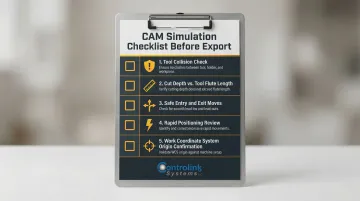
CAM simulation is your most important quality gate — but it's not foolproof. Programs that pass simulation can still crash real machines due to unmodeled fixtures, thermal expansion, or incorrect G54-G59 work offsets.
Export G-Code Using the Correct Post-Processor
After toolpath verification, CAM software uses a machine-specific post-processor to export the toolpaths as G-code formatted for your specific controller. Using the wrong post-processor produces code that a machine may execute incorrectly or reject outright.
Critical post-processor considerations:
- Select the exact post-processor for your machine brand and controller model
- Verify the output file extension matches what your controller expects (.nc, .tap, .cnc)
- Review the first few lines of the G-code to confirm it includes the correct initialization commands
- Check that tool change commands (M06) and spindle commands (M03/M04) match your machine's syntax
Never assume a G-code file written for one machine will work on another, even if they're the same brand. Controller firmware versions and custom macro configurations can cause unexpected behavior.
Send the File to Your CNC Machine
There are two primary methods of file delivery:
1. Direct USB/Memory Card Transfer (Common for Standalone Machines)
- Copy the G-code file to a USB drive or memory card
- Insert the media into the machine controller
- Navigate the controller's file browser to select and load the program
2. Networked/DNC Transfer (Standard for Production Environments)
- Files are sent from a central computer or server to one or more machines on the floor
- Eliminates the need for physical media and manual file copying
- Ensures operators always receive the latest engineering-approved file version
In shops running multiple machines, manual USB transfers lead to version confusion — operators accidentally load outdated or unoptimized G-code files. USB drives also expose legacy Windows CNC controllers to malware and BadUSB exploits.
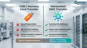
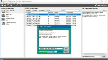
For shops managing programs across multiple machines, a dedicated DNC solution like Controlink Systems' DNC software delivers the correct, current file to each machine — eliminating the risk of machinists running outdated or unapproved programs.
Monitor and Complete the Cut
Before pressing cycle start, verify the following at the machine:
- Work offset (G54/G55) matches the physical setup and was measured correctly
- Tool in the spindle matches what the program expects (tool number and diameter)
- Material is secured and won't shift during cutting
- Coolant is functioning if required for the operation
Perform a dry run or single-block execution on first use of any new file. Single-block mode executes only one line of code at a time, stopping until the operator presses cycle start again, allowing for block-by-block verification.
During the cut, watch for:
- Unusual tool deflection or chatter
- Incorrect depths or surface finishes
- Unexpected pauses or error messages
- Excessive heat or smoke
Most of these trace back to CAM setup errors rather than machine faults. If you encounter problems, stop the machine immediately and review your toolpaths in CAM simulation.
After the job runs:
- Save any program edits made at the machine back to the master file to prevent version drift
- Document any changes in a revision log
- Update the CAM project if geometry or toolpath modifications are needed
This last step is critical in shops without a formal file management process. Running an old revision of a program because it wasn't clearly labeled is one of the most common real-world mistakes.
Common CNC File Formats and When to Use Each
Understanding which file format to use at each stage of the workflow prevents compatibility issues and ensures accurate machining.
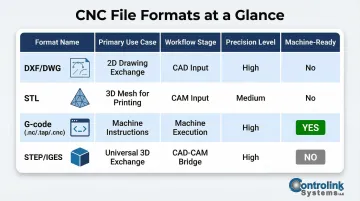
DXF/DWG: 2D Vector Formats
DXF and DWG are the standard design inputs for CAM software, particularly for flat-cut operations like routing, plasma cutting, waterjet, and laser cutting.
These formats store 2D geometry — lines, arcs, circles, and polylines — and are easily imported by most CAM applications. Created by Autodesk, they've become the industry default for 2D design exchange.
One thing beginners often miss: DXF and DWG files are not machine-ready. They still need to pass through CAM software to generate toolpaths and G-code before anything gets cut.
STL: 3D Mesh Format
STL is primarily a 3D printing format, though some CAM software can accept it as a milling input — with real trade-offs.
STL represents 3D surfaces using a mesh of triangles rather than true solid geometry. There's no dimensional precision metadata — just a faceted approximation of curves.
According to PCBWay's CNC machining guide, this triangulated structure lacks parametric data and true curves, making STL unsuitable for tight-tolerance work. A circle becomes a faceted polygon. For precision CNC machining, use solid-body formats like STEP or Parasolid instead.
G-code (.nc, .tap, .cnc): Machine Instruction Files
G-code is the actual file loaded into the CNC controller to run the machine. It's plain-text alphanumeric instructions — commands like G00, M03, X10.5 Y20.0 — that tell the machine exactly where to move and what to do.
Key things to know about G-code files:
- Dialects vary by machine brand (Fanuc, Haas, Siemens, Mazak)
- File extensions (.nc, .tap, .cnc) are interchangeable naming conventions
- The extension does not determine compatibility — the internal syntax does
This last point trips up beginners regularly. As CNC Code explains, renaming a .nc file doesn't change anything inside it. A file generated for a Haas controller will have the wrong dialect for a Fanuc machine — regardless of what the file is called.
STEP/IGES: Neutral CAD Formats
STEP and IGES exist to transfer 3D solid models between different CAD systems without losing geometric integrity. Both preserve precise solid geometry and parametric data, making them the right choice for importing into CAM software before generating toolpaths.
For any 3D CNC milling work, default to STEP or Parasolid as your CAM input. They maintain micron-level accuracy and prevent the toolpath errors that come from working with approximated mesh formats like STL.
Best Practices for Managing CNC Files on the Shop Floor
File management discipline is just as important as creating the file correctly in the first place. Poor file management drives scrap, rework, and machine crashes — often more than the programs themselves.
Establish a Naming Convention and Folder Structure
From day one, implement a consistent naming convention that includes:
- Part number or drawing number
- Revision level (Rev A, Rev B, etc.)
- Machine designation (if running multiple machines)
- Date of last modification (optional but helpful)
Example: 12345-RevB-Haas-VF2-2024-03-15.nc
This simple discipline prevents the most common real-world mistake: running an old revision of a program because it wasn't clearly labeled. Dimensional inconsistencies account for 22% of total rework costs in high-precision manufacturing, and a significant portion of this scrap is caused by running outdated G-code programs.
Always Run a Dry Run First
Run a dry run (no material, tool lifted above the workpiece) the first time a new or revised file is executed on a machine. Even a CAM-verified file can fail in real-world conditions due to:
- Fixture differences between simulation and reality
- Controller interpretation quirks
- Incorrect work offset entry
- Tool length measurement errors
Programs that pass CAM simulation can still crash real machines due to these factors. A dry run catches these issues before they cause damage.
Use Revision Control for CNC Programs
Treat CNC programs the same way engineering teams treat drawings:
- Maintain a master file location (not on individual machine controllers)
- Document all changes in a revision log
- Never allow machinists to save edited files over the master without an approval step
- Require engineering or programming approval before a new revision goes to production
For shops running multiple CNC machines, a DNC software system solves this problem at scale. It centralizes file storage, distributes programs directly to machines on demand, and logs every transfer — no USB drives, no manual copying, no version confusion. Controlink Systems' DNC software handles exactly this workflow, with access controls that prevent unauthorized edits and a centralized database that ensures every machinist pulls from the latest engineering-approved file.
Back Up CNC Files Regularly
CNC controllers can lose memory during power events, and an unrecoverable program that took hours to develop is a significant operational risk. Implement a backup strategy:
- Store master files on a network server with automatic backups
- Keep a secondary backup on external media (separate from the shop floor)
- Document the backup schedule and verify restoration procedures periodically
Never rely solely on files stored in machine controller memory. Controllers fail, memory cards corrupt, and power surges happen.
Optimize Toolpaths to Reduce Cycle Time and Tool Wear
Backups protect what you have — but optimized toolpaths determine what you get out of each run. Unoptimized CAM toolpaths that ignore varying cutter loads cause tool breakage and inflate cycle times. Physics-based NC simulation software that maintains constant chip thickness can reduce cycle times by 20–70% and double tool life.
You don't need to master toolpath optimization on day one. Start by understanding that feed rates, step-overs, and chip load settings directly affect both tool life and part quality — then revisit those parameters as you build experience.
Frequently Asked Questions
Can you CNC an STL file?
STL files can be used as a CAM input for CNC milling, but they must first be processed through CAM software to generate toolpaths—the STL itself cannot be sent directly to a CNC controller. STL files use mesh geometry rather than precise solid geometry, which can affect accuracy for tight-tolerance parts.
What is the difference between a CNC file and G-code?
"CNC file" is a broad term covering design files (CAD), toolpath files (CAM), and machine instruction files. G-code specifically refers to the final instruction set sent to and executed by the CNC controller—the plain-text commands that tell the machine exactly how to move.
What software do I need to create a CNC file from scratch?
You need a CAD tool to create the geometry and a CAM tool to generate G-code. Platforms like Fusion 360 combine both in one interface—a practical starting point for beginners that also eliminates file compatibility headaches between separate tools.
What file format does a CNC machine actually use?
Most CNC machines run G-code, which is exported from CAM software using a machine-specific post-processor. The file extension varies (.nc, .tap, .cnc) but the underlying format is G-code regardless of extension. The dialect and syntax must match your specific controller brand.
Can I edit a CNC file directly without going back to CAD/CAM?
Minor adjustments—feed rates, offsets—can be made directly in G-code using a text editor or the controller's edit function. Any geometry changes should go back through CAD/CAM and be re-posted, since manual edits to toolpaths can easily introduce crashes if the syntax is wrong.
How do I transfer a CNC file to my machine?
The two main methods are USB/memory card transfer for standalone machines and networked DNC transfer for multi-machine production environments. DNC is the better option when version control matters—it eliminates manual file copying and ensures operators always run the latest approved program.