Introduction
A machinist stands at the controller, ready to adjust a feed rate that's been causing chatter on a production part. One misplaced decimal point, one wrong modal code, and the next cycle could send a $15,000 tool crashing into a fixture—or scrap an entire batch of parts worth thousands of dollars. According to Siemens' 2024 True Cost of Downtime report, unplanned CNC downtime costs manufacturers an average of $260,000 per hour, spiking to $2.3 million per hour in automotive facilities.
Editing a CNC program is fundamentally different from writing one from scratch. The program may already be running in production, and a bad edit doesn't just fail quietly—it can destroy tooling, scrap parts, or stop a line mid-shift. Industry data shows 15% of high-volume automotive shops experience rework, with 3-8% scrap rates largely tied to programming errors or wrong file versions.
The right process matters as much as technical accuracy. This guide covers everything from retrieving the correct program version to making safe edits at the controller, with simulation verification before any part runs.
Key Takeaways
- Always retrieve the correct program version, make targeted G-code changes, verify with simulation or dry run, then save with version control
- Always back up the original program before making any changes—no exceptions
- Edits can be made at the machine controller (MDI or edit mode) or offline using dedicated CNC editing software—each approach carries different risks
- Most errors stem from working with outdated files, skipping verification, or changing interdependent parameters without checking downstream effects
- DNC software centralizes program storage so machinists always pull the latest engineering-approved version, eliminating file confusion across machines
How to Edit a CNC Program: Step-by-Step
Step 1: Identify the Program and Retrieve the Correct Version
Locate the exact program number or file name tied to the part and operation being run. Cross-reference it against the current revision on the engineering drawing or job traveler. AS9100 Rev D (Clause 8.1.2) and ISO 9001:2015 (Clause 7.5) classify NC programs as controlled documented information, which means version control isn't optional in regulated environments.
The risk of editing a stale local copy versus the master file is significant. Shops using DNC software—like Controlink's CNC/DNC communications solution—can pull the latest engineering-approved program directly from a central server, eliminating version confusion. This centralized approach ensures that:
- Every machine accesses the same master file
- Outdated copies don't circulate on USB drives
- Engineering changes apply immediately across the floor
- Audit trails track who accessed which version
Step 2: Review the Program Structure Before Touching Anything
OEM controllers add proprietary rules on top of the ISO 6983-1:2009 baseline word-address format (N, G, X/Y/Z, F, S, T, M)—so read the full program, or at minimum the relevant section, before touching anything.
Key elements to identify:
- Tool calls (T-codes): Which tool is active and when it changes
- Work offsets (G54-G59): Where the machine thinks part zero is located
- Canned cycles (G81-G89): Drill cycles with embedded parameters
- Feed/speed blocks (F, S): Current cutting parameters
- Modal vs. non-modal codes: Which commands stay active until canceled
Identify the specific block or blocks that need to be changed—note the line/block number—and confirm that changing those lines won't create conflicts with earlier or later blocks. For example, changing a tool offset call (D-code) that's referenced multiple times requires checking every instance.
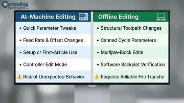
Step 3: Make the Edit—At the Machine or Offline
Two main editing environments exist:
(a) Directly at the CNC controller using MDI or program edit mode (b) Offline using dedicated CNC editing software (CIMCO Edit, Predator Editor, Notepad++ with G-code syntax)
When to use each approach:
| Method | Best For | Risks |
|---|---|---|
| At-Machine Editing | Quick parameter tweaks (feed rates, offset numbers) during setup or first-article inspection | Fanuc and Haas safety manuals warn against modifying programs in use—can cause unexpected machine behavior |
| Offline Editing | Structural changes (toolpath logic, canned cycle parameters, multiple-block edits) | Requires reliable file transfer and verification before running |
For at-machine edits:
- Navigate to the correct block using the controller's program navigation
- Enter edit mode (procedure varies by controller brand)
- Make the change carefully—watch for missing decimal points, incorrect axis letters, or dropped words
- Back up the program to an external source (USB, DNC server) before saving changes
- Confirm syntax is correct using the controller's diagnostic features
For offline edits:
- Open the file in editing software with G-code syntax highlighting
- Use search/find functions to locate exact block(s)—don't rely on scrolling
- Make the change and run a visual or software-based check on the modified section
- Save under a new revision name (e.g., O1001_REV2 or with date suffix)
- Transfer back to the machine using DNC software or verified USB transfer
Step 4: Verify the Edited Program Before Running
Run a graphical simulation or backplot within the editing software or CAM system to visually confirm the toolpath still behaves as expected. According to CGTech/Vericut, unverified prove-outs can cost $24,000 per month before you factor in scrapped parts, broken tooling, or damaged fixtures.
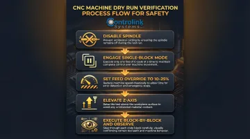
If no simulation tool is available:
- Perform a dry run at the machine
- Use single-block mode with spindle off
- Set feed override to 10-25% of programmed rate
- Elevate Z-axis or use rapid traverse override
- Watch each block execute carefully
Critical verification checklist:
- Does the tool move to the expected coordinates?
- Are feed rates and spindle speeds within safe ranges?
- Do work offsets position the tool correctly relative to the part?
- Are canned cycle depths and retracts correct?
Skipping verification is the most common cause of post-edit crashes. A feed rate change in the wrong block context can move the tool into the fixture at full speed.
Step 5: Save, Version-Control, and Re-Upload
Save the edited program with a clearly updated revision identifier so the change is traceable. AS9100 Rev D configuration management requirements require shops to track every revision to a program: who changed it, when, and why.
Revision naming best practices:
- Append revision number: O1001_REV2, O1001_REV3
- Include date suffix: O1001_2025-04-15
- Use engineering change order (ECO) numbers: O1001_ECO_12345
Upload the revised program back to the machine or central DNC server, and confirm the machine is running the updated file (not a cached version). Document the change in the program header or a shop log, as shown below.
Example program header comment:
(REV2 - 2025-04-15 - J.Smith - Reduced feed rate in Block N0125 from F20.0 to F15.0 to eliminate chatter on aluminum part)
When Should You Edit a CNC Program vs. Reprogram from Scratch?
Editing an existing CNC program is appropriate for:
- Correcting a feed rate or spindle speed
- Updating a tool number or offset reference
- Adjusting a depth of cut by a few thousandths
- Fixing a positional error (X/Y/Z coordinate)
- Adapting a program for slightly different material or machine
These are changes that do not alter the fundamental geometry or toolpath logic. The program's structure remains intact. You're tuning parameters, not redesigning the process.
Reprogramming from scratch (or regenerating from CAM) is the right call when:
- Part geometry has changed significantly (new features, different dimensions)
- Machining strategy needs redesign (different tool approach, new fixture setup)
- Machine or tooling setup has fundamentally changed (different spindle, tool changer configuration)
- Existing program has accumulated so many patches it's no longer readable or trustworthy
Once you've confirmed an edit is the right path, getting that change to the right machine efficiently is the next challenge. For shops running high-mix, low-volume production, centralized program management via DNC software makes small edits more practical. Updated programs can be pushed to specific machines instantly, rather than manually walking files across the floor. This eliminates the risk of running outdated versions and reduces changeover time between jobs.
What You Need Before Editing a CNC Program
Skipping preparation is how a small offset correction turns into a scrapped part. Before touching a single line of code, confirm you have the right tools, reference materials, and access in place.
Equipment and Access Requirements
For at-machine editing, you need:
- Access to the CNC controller's edit mode
- Required operator authorization (password or permission level)
- Familiarity with the specific controller's interface (Fanuc, Haas, Siemens, or Mazak)
For offline editing, you need:
- A computer with compatible editing or CAM software
- A reliable file transfer method (USB, DNC serial link, or Ethernet)
- Backup storage for the original program files
Reference Materials and File Readiness
Confirm you have:
- Current part drawing or engineering revision
- Original program file (backed up before any changes)
- Tool sheet or setup sheet (listing tool numbers, offsets, materials)
- Knowledge of the specific controller's G-code dialect (dialects vary — what works on Fanuc may not work on Siemens)
Controller OEM manuals document critical differences—for example, Haas controllers enforce that "you cannot put two G-codes from the same group in the same program block," while Siemens has a 512-character block limit.
Skill and Safety Readiness
The editor needs functional G-code literacy before making changes:
- Difference between modal and non-modal codes
- Word address format (N, G, X/Y/Z, F, S, T, M)
- Which code types the edit involves
- How changing one parameter affects downstream blocks
Editing without this foundation creates both safety and quality risks. Skill gaps don't just cause bad parts — they also drive unnecessary downtime. Industry data shows 35-40% of unplanned stops stem from addressable alarm codes, faults an operator with the right reference could clear in under 15 minutes.
Key Parameters and Code Sections to Review When Editing a CNC Program
Editing a CNC program means more than changing a single value. Four parameter categories — feed rates, tool offsets, work coordinates, and canned cycles — each carry cascading effects. A change in one often invalidates something else in the same block or a later line. Here's what to review in each.
Feed Rates and Spindle Speeds (F-codes and S-codes)
Feed rate (F) and spindle speed (S) directly affect surface finish, tool life, cycle time, and part accuracy — and they're the most commonly edited values in production programs. Both are derived values, not arbitrary inputs:
- Spindle Speed (RPM):
(Surface Feet per Minute × 3.82) / Tool Diameter(Kennametal) - Feed Rate:
RPM × Chip Load × Number of Teeth
Increasing feed rate without considering material, tool diameter, or depth of cut can cause tool breakage or poor finish. Seco Tools research shows that improper speeds and feeds are a leading cause of excessive tool wear. Cutting feed too low wastes cycle time and reduces throughput.

Before saving any F or S edit:
- Check the material spec and tooling recommendation
- Verify the change doesn't exceed the tool's maximum chipload
- Consider the effect on surface finish requirements
- Test with a dry run or single-block execution
Tool Offsets and Compensation (D-codes, G41/G42 for radius, G43/G44 for length)
Tool offset codes reference stored values in the controller's offset table. Editing the G-code call (D01, H01) without updating the corresponding register — or vice versa — creates a mismatch that causes dimensional errors or crashes.
The four offset types to know:
- G41/G42: Cutter radius compensation (left/right of programmed path)
- G43/G44: Tool length compensation (positive/negative offset)
- D-codes: Reference to radius offset register
- H-codes: Reference to length offset register
Industrial Monitor Direct traced one crash to G41 being active during a conventional cutting operation. The tool landed on the wrong side of the programmed path and shifted the finished diameter outward by roughly the full tool diameter.
The fix is straightforward: always cross-check code edits against the physical offset table on the machine. Change D01 to D02, and confirm that register D02 holds the correct radius for the new tool before running.
Work Coordinate Systems and Datum Offsets (G54–G59)
The work offset (G54–G59) tells the machine where part zero is. Switch work offsets in the program without verifying the controller's coordinate register, and the entire machining operation shifts by the difference between those two offsets.
Standard usage:
- G54: Primary work coordinate system (most common)
- G55–G59: Additional systems for multi-part setups or fixture offsets
In a CNCCode post-mortem analysis, the program called G54 but the machine had G55 active. The command G01 X0 Y0 Z-5 drove the tool into the fixture rather than the part because part zero was in a completely different location.
Before editing any work offset call:
- Confirm the physical setup matches the programmed offset
- Verify the coordinate register values in the controller
- Run a dry run with the Z-axis elevated to check positioning
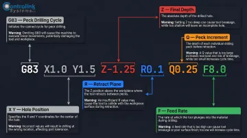
Canned Cycles and Fixed Cycle Parameters (G81–G89 drill cycles, G83 peck drilling)
Canned cycle blocks pack multiple parameters — R-plane, Z-depth, Q increment, P dwell — into a single line. Editing one parameter without reviewing the full block leaves the rest of the values unvalidated, which is where most canned-cycle errors originate.
Parameters in a typical canned cycle block:
- R: Retract plane (safe height above part)
- Z: Final depth of hole or feature
- Q: Peck increment (for G83 peck drilling)
- P: Dwell time at bottom of hole (for G82, G89)
- F: Feed rate for the cycle
A missing decimal in Z is a common culprit. CNCCode analyzed a crash where the controller read "Z15" as Z1.5 instead of Z15.0, sending the tool into the fixture. A Q value left unchanged during a G83 edit is equally dangerous — wrong peck increment leads to chip packing and broken tools.
When editing any canned cycle block:
- Read and verify the entire block, not just the parameter you're changing
- Check that R-plane is safely above the part surface
- Confirm Z-depth matches the drawing specification
- Verify Q increment suits the material and hole depth
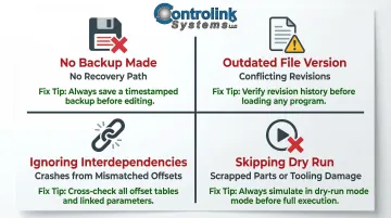
Common Mistakes When Editing CNC Programs
Editing without backing up the original:
The most avoidable mistake. Always save a copy of the unmodified program before making any changes. Without a backup, a bad edit has no recovery path. Store backups on a central DNC server, external USB drive, or network location—not just in the machine's memory.
Working from an outdated or incorrect program version:
Editing a file that isn't the current approved revision means the edit may conflict with changes already made elsewhere, or the "fixed" program is based on an obsolete toolpath. Industry research shows that many reworks arise from poor CAM programming or operators inputting the wrong tool length, zero point, or fixture offset. Establish a single source of truth for program files — preferably a DNC server with version control — and always pull from it before editing.
Changing a value in isolation without checking interdependencies:
A feed rate change in one block may need to match other blocks in the same toolpath. A tool number change must be accompanied by an offset register check. Failing to trace the downstream effects of an edit is a leading cause of crashes.
For instance, changing T01 to T02 in the tool call block without updating the corresponding H01 offset reference to H02 leaves the program referencing the wrong length offset — causing Z-depth errors.
Skipping the dry run or simulation after editing:
Even experienced programmers run a dry run after any edit. Assuming the change is too small to affect the overall motion is a false economy — one dropped decimal or wrong axis letter can have major consequences. Fanuc's Series 30i manual explicitly states: "Check the program in the single block mode by executing the program block by block." That advice applies whether you changed one line or twenty.
Troubleshooting Common CNC Program Edit Issues
Even careful edits can trigger problems the first time a modified program runs. Recognizing the likely cause of each symptom speeds up diagnosis and gets the machine back on track faster.
Problem: Machine alarms or stops on the edited block
Most often, a syntax error in the edited line is the culprit — a missing decimal point, an unrecognized word address, for example calling G91 incremental mode when absolute is expected, or a missing end-of-block character.
Fix:
- Re-examine the exact modified block character by character
- Compare against the controller's programming manual for valid syntax
- Check the block before and after the edit for modal codes that may now conflict
- Verify that the controller is in the expected mode (absolute vs. incremental, inch vs. metric)
Problem: Part dimensions are off after editing a feed/offset value
The edit likely changed a code reference without updating the corresponding controller register, or cutter compensation is active and the new toolpath doesn't account for it correctly.
Fix:
- Verify the offset table values on the machine match what the program expects
- Re-check whether cutter radius compensation (G41/G42) is correctly applied for the edited geometry
- Confirm that the tool diameter in the offset register matches the physical tool
- Run a test cut on scrap material to verify dimensional accuracy
Problem: Program runs but toolpath looks wrong during dry run
A work offset or coordinate reference was likely changed in the program without updating the machine's coordinate register, or a G90/G91 mode switch is incorrect after the edit.
Steps to Fix:
- Backplot or simulate the edited program again in offline software
- Verify G90/G91 state throughout the edited section
- Confirm the active work coordinate system register (G54-G59) matches the edited code
- Check that the program hasn't inadvertently switched between absolute and incremental positioning
Frequently Asked Questions
Can you edit a CNC program directly at the machine controller?
Most CNC controllers (Fanuc, Haas, Siemens, Mazak) have a built-in edit mode that allows operators to modify program blocks directly in the machine's memory. This is practical for quick, minor edits like feed rate adjustments or offset number changes, but carries risk if no backup is made first and is not suitable for complex structural changes.
What is the safest way to test a CNC program after editing it?
Start by simulating or backplotting the program in software to catch visual errors. Then run a machine dry run in single-block mode with the spindle disabled and feed rate override at 10–25% before a full production run.
How do I know which G-code blocks to edit for a specific change?
Navigate using tool call blocks (T-codes), work offset calls (G54–G59), and operation sequence comments. Offline editing software with search/find functions and syntax highlighting makes locating specific code words much faster than scrolling through the program at the machine.
What software is commonly used to edit CNC programs offline?
CIMCO Edit and Predator Editor are industry-standard tools offering backplot visualization, syntax checking, and DNC transfer capabilities. Fusion 360 CAM includes G-code editing features, and basic text editors like Notepad++ with G-code plugins work for simple hand-coding tasks.
How do I prevent version control problems with CNC programs across multiple machines?
Centralized DNC software stores master program files on a server and transfers them to machines on demand, so machinists always run the latest engineering-approved revision. Controlink Systems' CNC/DNC software is built for this use case, providing centralized program management that reduces scrap and downtime from version errors.
What is the difference between editing tool offsets in the program vs. at the controller?
Editing offset values directly in the G-code (the D or H register call number) changes which offset table entry the program references, while editing offset values at the controller changes the stored dimensional value in that entry. Both approaches affect the outcome but in different ways, and confusing the two is a common source of dimensional errors.