CNC machines operate under extreme loads and tight tolerances, making gradual component degradation inevitable. Spindle bearings wear, servo drives misalign, and coolant systems degrade—all invisibly, until catastrophic failure stops production mid-shift. Without proper monitoring, these failures trigger emergency repairs, scrapped parts, overtime labor, and expedited shipping costs that dwarf the price of the failed component itself.
This guide covers what condition monitoring means for CNC machines, which components demand the closest attention, which monitoring techniques deliver the best early warnings, and how to build a practical program from the ground up.
TLDR: Key Takeaways
- Condition monitoring detects developing faults 12–18 months before failure, turning emergency repairs into planned maintenance events
- Feed drives cause 38% of CNC stoppages; spindles and tool changers account for another 26%
- Vibration analysis, motor current monitoring, and thermal imaging provide the earliest fault detection
- Start by ranking machines by criticality, then capture healthy baseline measurements before faults develop
- Results include a 30–50% reduction in unplanned downtime, fewer scrapped parts, and longer machine life
What Is Condition Monitoring in CNC Machines?
Condition monitoring is the continuous or periodic measurement of key parameters—vibration, temperature, motor current, acoustic emission—to assess the health of machine components in real time. It transforms raw sensor data into clear, usable signals about when a bearing, spindle, or drive system is degrading.
From Reactive to Predictive Maintenance
Traditional maintenance strategies fall into two categories:
- Reactive maintenance: Fix components after they break, accepting unplanned downtime and collateral damage
- Preventive maintenance: Replace parts on a fixed calendar schedule, often discarding healthy components prematurely
Condition monitoring introduces a third approach: predictive maintenance. It applies the P-F curve concept—the interval between when a fault begins developing (Potential Failure) and when it causes complete breakdown (Functional Failure). Vibration analysis, for example, can detect bearing wear 12 to 18 months before functional failure, creating a detection window that allows planned intervention instead of emergency repairs.
Why CNC Machines Demand Condition Monitoring
CNC machines combine high-speed rotating spindles (often exceeding 10,000 RPM), multi-axis servo drives, precision bearings, and complex hydraulic and coolant systems. Each subsystem degrades in measurable, characteristic ways before outright failure:
- Bearings produce distinct vibration frequencies as surface defects develop
- Servo motors draw abnormal current when mechanical resistance increases
- Spindle housings generate excess heat when lubrication breaks down
These early-stage signatures are invisible to operators but clearly detectable by sensors. The catch: those sensors must be in place and properly configured to capture them.
Why CNC Downtime Costs More Than You Think
The True Cost Multiplier
Most shops calculate downtime using visible metrics: machine hourly rates ($75–$200/hour for a standard vertical mill) and operator idle wages ($25–$45/hour). But these direct costs represent less than half the financial burden.
According to Siemens research analyzing Fortune Global 500 companies, unplanned downtime costs large manufacturers an average of $260,000 per hour. In automotive manufacturing, this figure reaches $2.3 million per hour (more than $600 per second).
Hidden costs act as a 1.5x to 10x multiplier:
- Scrapped parts: A degraded spindle bearing introduces micro-vibrations that ruin dimensional accuracy and surface finish long before the bearing seizes
- Overtime recovery: Catching up on lost production requires paying maintenance crews and operators at 1.5x rates
- Expedited logistics: Emergency replacement parts and rush shipping carry premium fees
- SLA penalties: Missing contractual delivery deadlines trigger financial penalties from Tier-1 customers
Predictable Failure Points
Understanding where costs come from is only useful if you know where failures originate. A comprehensive German study by Fleischer et al. analyzed maintenance data from 250 CNC machine tools in automotive production and found that downtime causes are both predictable and monitorable:
- Feed drives and servo axes: 38% of all machine stoppages
- Main spindles and tool changers: 26% of stoppages
- Electronics: 23%
- Fluids (coolant/hydraulics): 13%
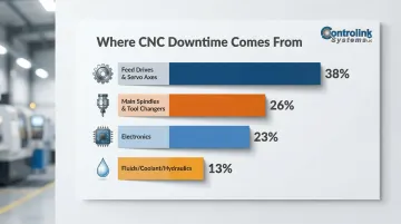
Feed drives, spindles, and tool changers together account for nearly two-thirds of all CNC downtime. Each produces detectable warning signs weeks or months before failure.
Key CNC Components That Require Condition Monitoring
Spindles and Spindle Bearings
The spindle is the most critical and vulnerable component in any CNC machine. It operates under variable cutting forces, thermal stress, and high RPM simultaneously. Bearing defects in the spindle are the most common malfunction encountered in CNC machines and can develop undetected for weeks.
Why L10 Calculations Fall Short
Spindle bearing life is theoretically predicted using the L10 rating (the number of revolutions 90% of identical bearings will reach under ideal conditions). ISO 281 acknowledges that L10 calculations have severe limitations: they assume perfect lubrication and cleanliness, and they model only subsurface fatigue.
In reality, CNC spindle bearings face:
- Variable speeds and high loads
- Kinematic starvation (insufficient lubricant film at high speeds)
- Contamination from coolant, metal fines, and swarf
These factors cause surface distress and adhesive wear (seizure) rather than traditional subsurface fatigue. According to SKF research, the L10 life ratio between a clean bearing and a heavily contaminated one can be as much as 500:1. This means a bearing rated for 10,000 hours might fail in just 20 hours if contamination enters the bearing stack.
Drive Systems and Servo Axes
Servo axes are the leading cause of machine stoppages, accounting for 38% of failures in the German automotive study. These systems are prone to:
- Abnormal motor current draw from increased mechanical resistance
- Vibration signatures indicating misalignment or backlash
- Unusual thermal output from bearing wear or motor overload
Because servo drives are distributed across multiple axes (X, Y, Z, and rotary), monitoring programs must cover each axis individually rather than relying on a single measurement point.
Tooling and Tool Changers
Tool changers account for roughly a quarter of all CNC downtime — grouped alongside spindle malfunctions in failure studies. Worn or improperly seated tooling introduces vibration that shows up in spindle monitoring data. Tool condition also affects surface finish and dimensional accuracy well before catastrophic failure: degraded tooling causes quality problems long before it stops the machine.
Coolant and Lubrication Systems
Coolant and lubrication quality directly affects bearing and spindle life. Degraded coolant causes thermal drift and corrosion; insufficient lubrication accelerates bearing wear.
Tramp oil and bacterial growth are common culprits. The contamination cycle typically unfolds like this:
- Tramp oil (leaked hydraulic fluid or way lube) floats on water-based emulsions, sealing the sump from oxygen
- Anaerobic bacteria grow in the sealed sump, degrading coolant and lowering pH
- Reduced lubricity lets swarf and metal fines remain suspended in the fluid
- These abrasive particles bypass spindle seals and cause plastic deformation on bearing raceways
Oil and coolant analysis — though often overlooked — provides cost-effective early-warning signals of contamination, metallic wear particles, and pH imbalance.
Thermal Stability and Temperature
Thermal growth in the spindle and machine frame causes dimensional inaccuracies even before mechanical failure occurs. Temperature monitoring at key points — spindle housing, axis drives, coolant outlet — provides early indicators of:
- Abnormal friction from bearing wear
- Inadequate cooling from clogged passages or failing pumps
- Overload conditions from excessive cutting forces
According to Fluke's thermal imaging research, every 10°C increase in a motor's windings above its designed operating temperature cuts insulation life by 50%. In CNC spindles, abnormal temperature rises often indicate grease degradation, over-packing, or coolant ingress.
Condition Monitoring Techniques for CNC Machines
Vibration Analysis
Vibration monitoring is the most widely adopted and versatile technique for CNC machines. It detects wear, imbalance, misalignment, and fatigue in rotating components—especially spindle bearings—often weeks before failure.
How It Works:
Deteriorating components produce characteristic frequency signatures that can be trended over time. For example, a bearing with an outer race defect generates impacts each time a rolling element passes over the defect. The frequency of these impacts (Ball Pass Frequency Outer race, or BPFO) is mathematically predictable based on bearing geometry and shaft speed.
Envelope Analysis for Early Detection:
Standard broadband vibration (RMS) often fails to detect early-stage localized bearing faults because the impact energy is buried under general machine noise. Envelope Analysis (High Frequency Resonance Technique) filters out low-frequency noise and demodulates the signal to extract the periodic impacts of rolling elements hitting a raceway defect. Brüel & Kjær case studies demonstrate that envelope analysis can provide nearly six months of lead time before severe bearing damage occurs.
The Consistency Challenge:
Vibration signatures are highly speed- and load-dependent. Taking measurements during active cutting introduces massive variations due to tool engagement, material hardness, and chatter. To establish a valid trend, measurements must be taken under strict boundary conditions: idle rotation, constant speed, and no cutting load.
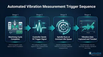
Automated Trigger Systems:
To achieve consistency without disrupting production, automated triggers send a measurement command at the end of each machining cycle. For example, a 5V signal from the CNC controller (triggered by a specific G-code like M30) captures vibration data while the spindle runs at a constant idle speed for a few seconds. This ensures parameters remain identical for every measurement, creating a reliable degradation trend.
Motor Current and Power Monitoring
Motor Current Signature Analysis (MCSA) is a non-invasive technique that uses data already available from the machine's servo drives. Abnormal current draw indicates increased mechanical resistance from worn bearings, misalignment, or a failing spindle motor—without requiring additional sensors.
Bearing faults cause microscopic oscillations in motor torque. These torque variations modulate the RMS current, producing distinct sidebands around the fundamental supply frequency in the stator current spectrum. Research published in Energies confirms that MCSA can successfully detect characteristic bearing fault frequencies (BPFO, BPFI, FTF, BSF) as well as rotor eccentricity and misalignment.
MCSA is cost-effective and immune to cutting fluid contamination. Its main limitation is signal sensitivity—fault signatures in the current spectrum carry very low energy and can be masked by inverter harmonics. Many shops pair MCSA with initial vibration envelope analysis to pinpoint fault frequencies first, then shift to continuous MCSA tracking once the target frequencies are confirmed.
Thermal Imaging and Temperature Sensors
Thermography (infrared imaging) identifies hot spots in spindle housings, bearings, and electrical panels. Periodic thermal scans provide snapshots of thermal anomalies, while continuous temperature sensors permanently mounted at key points enable real-time trending.
Recommended Monitoring Points:
- Spindle box shell and bearing housing (to detect localized bearing friction)
- Spindle motor shell and drive enclosures (to monitor stator/rotor heat generation)
- Coolant outlets and chiller feeds (to correlate thermal expansion with Z-axis displacement errors)
Oil and Coolant Analysis
Periodic fluid sampling identifies contamination, metallic wear particles, and pH imbalance—acting as a leading indicator of bearing and spindle wear. This technique is lower-frequency and lower-cost than continuous sensor monitoring, making it an effective complement to vibration and thermal analysis.
What to Test:
- Particulate contamination (swarf, metal fines)
- Tramp oil concentration
- pH levels (bacterial degradation indicator)
- Additive depletion
Software Integration and Real-Time Data Acquisition
The sensor techniques above generate data—but software is what turns that data into decisions. Connecting CNC machines via MTConnect, OPC UA, or serial communications to a centralized monitoring platform gives operators and managers a live view of machine health, utilization, and alert status across the entire shop floor.
MTConnect and OPC UA Adoption:
MTConnect is an open, royalty-free manufacturing communication standard supported natively or via adapters by major CNC builders including Mazak, Okuma, Haas, Fanuc, DMG Mori, and Siemens. The MTConnect Part 2.0 Device Information Model explicitly supports modeling sensor data (e.g., spindle vibration and temperature) directly associated with specific CNC components like rotary axes.
OPC UA provides read/write capabilities and is heavily championed in Europe. The VDMA and OPC Foundation have released companion specifications that standardize interfaces for machine status, job management, and tool management across the mechanical engineering sector.
Real-World Impact:
Case studies from MachineMetrics show that connecting CNCs to centralized platforms yields measurable results quickly. Avalign Technologies gained instant visibility into setup bottlenecks, improving Overall Equipment Effectiveness (OEE) from 25-30% to above 60%—a greater than 30% increase in equipment utilization—within five weeks.
Controlink Systems' process monitoring and CNC/DNC communication software connects machine health data directly into shop floor workflows, reducing manual inspection time. With native support for SQL databases, PLC hardware, and protocols including CAN, Modbus, Serial, Profinet, and EtherCAT, Controlink helps shops integrate condition monitoring into their existing infrastructure without overhauling what already works.
How to Build a CNC Condition Monitoring Program
Step 1 — Assess Machine Criticality
Rank machines by production impact. A machine that is the sole bottleneck for a critical part gets top priority for continuous monitoring; a general-purpose machine with a backup may only warrant periodic checks. This criticality ranking drives every subsequent decision.
Criticality Factors:
- Is this machine a production bottleneck?
- Does it produce high-value or safety-critical parts?
- Is there a backup machine available?
- What is the cost of unplanned downtime for this specific machine?
- How long does it take to source replacement parts?
Step 2 — Select Sensors and Monitoring Methods
Match monitoring technique to component and criticality level:
- High-criticality machines: Continuous vibration sensors on spindles and drives, real-time temperature monitoring
- Medium-criticality machines: End-of-cycle vibration measurements, periodic thermal scans
- Lower-priority assets: Monthly oil sampling, quarterly vibration checks
Basic Sensor Placement Principles:
- Mount accelerometers directly at bearing housings
- Avoid structural resonance nodes (points where vibration amplitude is amplified by the structure itself)
- Ensure sensors are securely mounted to prevent measurement drift
Step 3 — Establish Performance Baselines
Without a "healthy" reference measurement, anomaly detection is impossible. Capture baseline vibration signatures, temperature ranges, and current draw immediately after maintenance or machine qualification, then trend departures from that baseline over time.
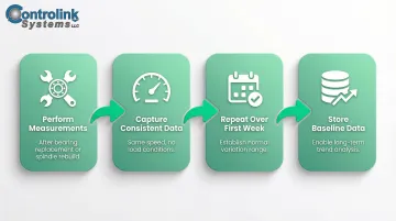
Baseline Capture Process:
- Perform measurements immediately after bearing replacement or spindle rebuild
- Capture data at consistent conditions (same speed, no load)
- Repeat measurements over the first week to establish normal variation
- Store baseline data for long-term trending
Step 4 — Set Alert Thresholds and Response Protocols
Define threshold levels that trigger escalating responses:
- First-level alert: Increased monitoring frequency (daily instead of weekly)
- Second-level alert: Schedule a maintenance intervention during next planned downtime
- Critical threshold: Immediate stop to prevent catastrophic failure
Alert thresholds should be machine-specific and validated against historical data rather than copied from generic guidelines. A spindle operating at 15,000 RPM will have different normal vibration levels than one operating at 3,000 RPM.
Step 5 — Integrate with Shop Floor Systems
Once thresholds are defined, that data becomes far more valuable when it's connected to the rest of your operation. Feeding machine health status into a DNC or MES system lets managers adjust scheduling around a machine flagged for upcoming maintenance rather than reacting to an emergency shutdown.
Controlink's shop floor automation and process monitoring software supports SQL databases, PLC hardware, and multiple communication protocols, helping shops build a connected monitoring setup where health data directly informs production scheduling and maintenance planning — not just alerts on a standalone screen.
Benefits of CNC Condition Monitoring
Reduced Unplanned Downtime and Extended Machine Life
Catching a degraded bearing before it seizes can mean a $2,000 bearing replacement instead of a $10,000+ spindle rebuild and days of lost production. Implementations of predictive maintenance and vibration monitoring in CNC environments typically yield a 30% to 50% reduction in unplanned downtime. In one industrial case study, a predictive maintenance model cut equipment downtime by 73% (from 450 hours to 120 hours annually).
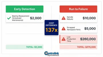
Cost Avoidance Example:
- Early detection: $2,000 bearing replacement during scheduled maintenance
- Run to failure: $10,000 spindle rebuild + $5,000 in scrapped aerospace parts + $260,000 in lost production time
Improved Part Quality and Lower Scrap Rates
A spindle with developing bearing wear introduces micro-vibrations that affect surface finish and dimensional accuracy well before catastrophic failure. Left unchecked, those micro-vibrations produce:
- Chatter marks and surface ripples
- Out-of-roundness and taper errors
- Dimensional drift that triggers customer rejections
Early detection stops the defect at the source — before a batch of out-of-tolerance parts reaches inspection or ships to a customer.
Better Resource Planning and Machine Utilization
When maintenance is planned based on actual machine health rather than arbitrary schedules, shops eliminate both emergency scrambles and unnecessary early replacement of healthy components. Predictive maintenance also enables:
- Stock critical components based on actual wear rates, not guesswork
- Schedule maintenance during nights or weekends to minimize production impact
- Replace parts based on condition, not calendar dates, avoiding premature disposal of healthy components
Frequently Asked Questions
What is condition monitoring in CNC machines?
Condition monitoring is the real-time or periodic measurement of parameters like vibration, temperature, and motor current to assess component health and detect developing faults before they cause machine failure or quality problems.
What is the most reliable machine health monitoring system?
There is no single universal answer—reliability depends on the components being monitored and the shop environment. Vibration analysis combined with software-based data integration is widely considered the most comprehensive approach for CNC machines, particularly for spindle and bearing health.
What are the most common failure points to monitor on a CNC machine?
Spindle bearings, servo drives and axes, and tool changers are the top three failure sources. Together, these three categories account for approximately 64% of all CNC machine stoppages, making them the highest-priority monitoring targets.
What is the difference between condition monitoring and predictive maintenance?
Condition monitoring is the data collection and analysis process; predictive maintenance is the maintenance strategy that uses condition monitoring data to schedule repairs before failure occurs. Without reliable condition data, predictive maintenance schedules are little more than educated guesses.
How often should CNC machines be monitored?
Monitoring frequency should match machine criticality and degradation rate. High-criticality spindles warrant continuous or end-of-cycle monitoring, while lower-priority systems may only need periodic checks monthly or quarterly.
Can condition monitoring reduce CNC scrap rates?
Yes. Spindle and bearing degradation introduces micro-vibration that affects surface finish and dimensional accuracy before visible failure. Catching this early prevents quality defects from reaching parts, reducing scrap and rework costs.