Introduction
If your shop still loads programs via USB stick or manual G-code entry, you're carrying more risk than you might realize. Rework rates can reach up to 15% in high-volume shops, driven largely by outdated program files and manual offset errors. Connecting your CNC machines to a computer keeps program versions consistent, reduces those errors, and opens the door to Direct Numerical Control (DNC) networking across the shop floor.
Getting there isn't always plug-and-play. Results vary based on machine age, available ports, connection method, and software configuration. This guide walks through each of those variables — hardware requirements, setup steps, key parameters, and common pitfalls — so you can build a reliable CNC-to-computer connection that actually holds.
Key Takeaways
- Most CNC machines use RS-232 serial ports — modern computers need a USB-to-Serial adapter or Serial-to-Ethernet converter to connect
- Four main connection methods exist: direct RS-232, USB adapter, Ethernet/LAN, and wireless WiFi—each suited to different shop sizes
- DNC software is required to send, receive, and manage G-code programs between computer and controller
- Serial parameters (baud rate, parity, data bits, stop bits) must match exactly on both ends or the connection fails
- Multi-machine shops need a dedicated DNC network to eliminate errors and control program versions across the floor
What You Need to Connect a CNC Machine to a Computer
Having the right hardware and software in place before starting prevents wasted time and mid-setup roadblocks. Identify your CNC machine's control model (Fanuc, Haas, Mazak, Okuma, Siemens, etc.)—each may have slightly different port types and parameter defaults.
Hardware Requirements
Physical items needed include:
- RS-232 serial cable (null modem, 25-pin or 9-pin depending on the CNC)
- USB-to-Serial adapter (if the computer has no native COM port)
- Serial-to-Ethernet or Serial-to-WiFi converter for wireless setups
Cable length limitations: The TIA/EIA-232-F standard specifies a maximum capacitive load of 2500 pF rather than a strict distance limit. Typical communication cables have 50 pF per meter, allowing approximately 50 feet (15 meters) without signal degradation. Using low-capacitance shielded cables extends this range significantly.
Software Requirements
A computer needs DNC/CNC communication software to manage program transfers—without it, even a physically connected machine cannot reliably send or receive files.
Core software requirements include:
- USB-to-Serial drivers — Windows often requires these before recognizing an adapter as a COM port
- DNC/CNC communication software — manages file transfers, G-code program libraries, and machine connections
- Machine-specific parameter profiles — baud rate, parity, stop bits, and handshake settings for your controller
Controlink Systems' DNC software is built for shop-floor environments, supporting multiple machine connections and G-code program management. Machinists always pull the latest engineering-approved files—no more walking programs across the floor on a USB drive.
Step-by-Step: How to Connect a CNC Machine to a Computer
Step 1: Identify the CNC Controller's Communication Port and Settings
Locate the communication port on the CNC machine. Most machines (Haas, Mazak, Fanuc, Okuma, Mori Seiki) have a DB-25 (25-pin) or DB-9 (9-pin) RS-232 serial port. Check the CNC's settings panel or operator manual to confirm port type.
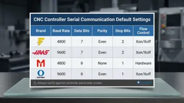
Note the machine's serial communication parameters — baud rate, data bits, parity, and stop bits (example: 9600, 8, None, 1). Match these exactly when configuring your DNC software.
Common defaults by controller brand:
| Controller Brand | Baud Rate | Data Bits | Parity | Stop Bits | Flow Control |
|---|---|---|---|---|---|
| Fanuc (0i, 16, 18) | 4800 / 9600 | 7 | Even | 1 or 2 | XON/XOFF |
| Haas (Classic) | 9600 / 115200 | 7 or 8 | Even or None | 1 or 2 | XON/XOFF |
| Mazak (Mazatrol) | 4800 / 9600 | 8 | None | 2 | XON/XOFF |
| Okuma (OSP) | 4800 / 9600 | 8 | None | 1 | XON/XOFF |
Step 2: Set Up the Hardware Interface
For computers with native RS-232 ports: Connect a null modem serial cable directly between the computer and CNC. If using a 25-pin port, a DB-25-to-DB-9 adapter will be required.
For computers without serial ports (most modern PCs and laptops): Install a USB-to-Serial adapter, then load the manufacturer's driver. Verify the adapter appears as a COM port in Windows Device Manager under "Ports."
Critical warning: Windows Update actively targets counterfeit FTDI and Prolific chips, which can brick adapters or inject garbage data into your G-code stream. Always source adapters from authorized distributors.
For wireless setups: Connect a Serial-to-WiFi converter to the CNC's serial port, power the converter, and configure it to join the shop's WiFi network via the converter's web-based admin panel.
Step 3: Configure the COM Port on the Computer
Open Windows Device Manager and note the COM port number assigned to the USB-to-Serial adapter or virtual COM port (for example, COM3 or COM5). Enter this number into your DNC communication software.
Before moving on, confirm these COM port settings in Device Manager match the values from Step 1:
- Baud rate — must equal the controller's setting exactly
- Data bits — typically 7 or 8 depending on brand
- Parity — Even or None (most common)
- Stop bits — 1 or 2 per controller spec
- Flow control — XON/XOFF for most shop machines
Mismatched settings are the most frequent cause of failed transfers.
Step 4: Install and Configure DNC Communication Software
Install DNC software on the computer, select the COM port identified in Step 3, and configure the serial parameters to match the CNC's settings.
Run a test transfer before going live. Send a small, known-good G-code program from the computer to the CNC — or perform a loopback test by shorting the TX and RX pins on the cable — to confirm two-way communication before loading any production programs.
CNC-to-Computer Connection Methods: Which Is Right for Your Shop?
The right connection method depends on shop layout, machine age, number of machines, and whether wireless flexibility or wired reliability is the priority. No single method fits all environments.
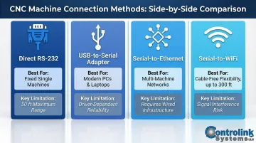
Direct RS-232 Serial Connection
- Best for older CNC machines in fixed locations, single-machine setups, or shops where a dedicated PC can sit within 50 feet of the machine
- Cable length is limited to ~50 feet with no network flexibility
- Requires a dedicated serial port — increasingly rare on modern computers
USB-to-Serial Adapter Connection
- Best for shops using modern PCs or laptops without native serial ports; a low-cost bridge compatible with most CNC brands
- Adapter quality matters — cheap adapters cause intermittent data errors
- Always verify driver compatibility with your current Windows version before purchasing
Serial-to-Ethernet or Serial-to-WiFi Connection
- Best for machines located far from the control PC, multi-machine DNC networks, or shops avoiding long cable runs across the floor
A Serial-to-WiFi converter attaches to the CNC's RS-232 port, connects to the shop's WiFi network, and creates a virtual COM port on the PC. Industrial device servers from Moxa, Digi, and Lantronix use RFC2217 or proprietary drivers to map TCP/IP sockets to virtual COM ports. Effective range is typically up to 300 feet, extendable with access points.
A few trade-offs to plan for:
- Initial configuration (IP address, port settings, virtual COM port creation) is more involved than a direct cable
- Requires stable WiFi coverage throughout the shop
- Heavy metal machinery causes significant signal attenuation — 2.4 GHz is often more reliable than 5 GHz on crowded shop floors
Key Parameters That Affect CNC-to-Computer Communication
The physical connection is only half the equation. Even a perfect cable setup fails if the software parameters on both ends don't match — mismatched settings produce garbled data, incomplete transfers, or total silence from the controller.
Baud Rate
Baud rate controls how fast data moves over the serial line. Common CNC values are 2400, 4800, 9600, 19200, and 115200 — and if the CNC and computer aren't set to the same rate, the data is unreadable on arrival.
Setting baud rate too high for an older machine or a long cable run introduces transmission errors. The TIA/EIA-232-F standard limits the maximum slew rate to 30 V/µs to prevent crosstalk. Start with the CNC's documented default and adjust upward only if needed. Baud rate, though, is just one piece — how each data packet is structured matters just as much.
Data Bits, Parity, and Stop Bits
These three settings define the structure of each transmitted data packet. A common default is 8N1 (8 data bits, no parity, 1 stop bit), but many legacy CNCs — particularly Fanuc and Haas — default to 7E1 or 7E2 (7 data bits, Even parity).
One mismatch here corrupts every packet received. Always verify against the CNC controller's parameter screen rather than guessing based on machine brand.
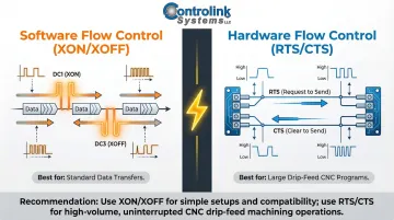
Flow Control (Handshaking)
Flow control tells the computer when to pause or resume transmission as the CNC's buffer fills. Two types exist:
- Software Flow Control (XON/XOFF): Uses in-band ASCII characters (DC1 for XON, DC3 for XOFF) transmitted over the standard data lines
- Hardware Flow Control (RTS/CTS): Uses dedicated physical voltage wires (Request to Send / Clear to Send) to toggle transmission
Using the wrong type cuts programs off mid-transfer. Haas and Fanuc controllers each have specific handshaking requirements — check the controller documentation before assuming a default. For drip-feeding large 3D surfacing programs, hardware flow control is far more reliable, since it reacts instantly to buffer limits rather than waiting for in-band signals.
Common Mistakes and How to Troubleshoot CNC Connection Issues
Most CNC connection failures come down to a handful of avoidable mistakes. Knowing what to watch for saves hours of troubleshooting.
Common Mistakes When Connecting a CNC Machine to a Computer
- Wrong cable type: Both the PC and CNC controller act as Data Terminal Equipment (DTE), so the Transmit and Receive lines must be crossed. A straight-through cable produces no data flow — you need a null modem (crossover) cable.
- Missing or outdated USB-to-Serial drivers: Most Windows 10/11 compatibility problems trace back to mismatched drivers. Install the driver from the manufacturer's website before plugging in the adapter.
- Partial serial parameter match: Operators often set the baud rate correctly but overlook parity or flow control. Any mismatch — even a single setting — causes partial transfers or corrupted program files.
Troubleshooting CNC Connection Issues
Problem: No communication / CNC does not respond
- Likely Cause: Wrong COM port selected in software, cable not fully seated, or adapter driver not installed correctly
- What to Check: Verify the COM port number in Windows Device Manager matches what's entered in the DNC software; re-seat all connectors; uninstall and reinstall the USB-to-Serial driver
Problem: Garbled or incomplete program transfer
- Likely Cause: Serial parameter mismatch between the CNC controller and the computer's communication software
- What to Check: Cross-reference baud rate, data bits, parity, stop bits, and flow control on both the CNC controller and DNC software — correct any discrepancy, then retry with a test file
Problem: Intermittent connection drops or data errors
- Likely Cause: Low-quality USB-to-Serial adapter, cable too long for the baud rate, or WiFi signal interference (for wireless setups)
- What to Check: Replace the adapter with a higher-quality alternative; reduce cable length or lower the baud rate; for WiFi setups, check signal strength at the machine location and consider adding a WiFi access point nearby
Frequently Asked Questions
How do you setup a CNC machine?
CNC machine setup involves physically installing the machine, powering it up, loading tooling, setting work offsets, and connecting it to a computer or DNC system to transfer G-code programs. Getting the communication connection right is what makes the rest of the setup usable.
What software do you need for a CNC machine?
Two main software layers are needed: CAD/CAM software (to design parts and generate G-code) and DNC/communication software (to transfer G-code programs to the CNC controller). For basic setups, DNC software alone suffices if an engineering workstation handles the CAD/CAM work.
Can you run a CNC machine from a laptop?
Yes, a laptop can connect to and control a CNC machine using a USB-to-Serial adapter and DNC communication software. A laptop is adequate for program transfer, but a dedicated workstation with fast CPU, SSD, and dedicated GPU is recommended for CAD/CAM work.
How do computer programs drive a CNC machine?
G-code programs (sequences of movement and machine commands) are created in CAM software, transferred to the CNC controller via DNC software, and interpreted by the controller to drive the machine's axes, spindle, and other outputs in precise sequences.
How to get data from a CNC machine?
You can retrieve data by uploading programs from the controller to your computer via DNC software over the same RS-232 or network connection. Some advanced DNC systems also support real-time machine monitoring for shop floor analytics.
What are the communication protocols for CNC machines?
The most common protocol is RS-232 serial communication, but modern shops also use RS-485, Ethernet/TCP-IP, MTConnect, and FANUC FOCAS. The protocol supported depends on the CNC controller's age and model. MTConnect is a read-only standard designed to pull data from the CNC—it cannot send programs to the machine, so DNC remains mandatory for two-way communication.