Introduction
Manufacturing engineers and plant managers face a persistent challenge: transforming a control concept into a fully operational automation system that performs reliably under real production conditions. In environments ranging from CNC machining and stamping to automotive assembly and process control, the difference between a system that works and one that fails often comes down to how thoroughly three interconnected phases—design, programming, and commissioning—are executed.
The industrial control system (ICS) lifecycle is frequently referenced but rarely explained as an integrated process. Design defines what the system must do and how it's structured. Programming translates those specifications into executable logic, while commissioning validates that the installed system performs as designed under actual production conditions.
When any one of these phases is rushed or treated as an afterthought, the consequences ripple through the entire project — equipment damage, schedule overruns, and rework costs that routinely exceed the original project budget.
This article explains how design feeds programming, how programming enables commissioning, and what affects outcomes at each stage—with a focus on the practical realities manufacturing teams face when bringing control systems online.
Key Takeaways
- Design, programming, and commissioning are sequential but interdependent—skipping any one compromises the entire system
- Each phase has a distinct role: design sets requirements, programming converts them into control logic, and commissioning confirms the system works under real conditions
- Functional specifications, I/O mapping, communication protocols, and safety interlocks must all be locked in before programming starts
- Virtual commissioning reduces on-site time by up to 70% and cuts physical rework by 40-50%
- Approximately 80% of factory test failures stem from incomplete documentation, not equipment defects
What Is the Design, Programming, and Commissioning Process for Industrial Control Systems?
The ICS lifecycle is the structured sequence through which an automation or process control system moves from concept to operation. It covers three distinct phases:
- Design — specifying system architecture, I/O requirements, and control logic based on process objectives
- Programming — coding and configuring the control logic, HMI interfaces, and communication protocols
- Commissioning — verifying the installed system operates correctly under real conditions before handoff
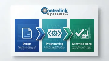
The goal is a commissioned ICS that controls machinery, processes, or data flows with the precision, safety, and repeatability the application demands.
This process differs from general software development or IT system deployment in ways that matter on the plant floor. ICS development is tied to physical hardware, real-time performance requirements, and safety-critical validation standards that generic software projects never encounter. A web application can be patched after deployment. A control system failure mid-production can halt an entire line, damage tooling, or put personnel at risk — which is why the sequence from design through commissioning must be executed correctly the first time.
Why This Process Matters in Manufacturing Environments
Manufacturing places demands on control systems that office IT infrastructure never encounters. A system that works perfectly in a clean test lab can fail immediately on the production floor. Shop environments introduce conditions that expose every weakness in design and programming:
- Cycle times measured in milliseconds with zero tolerance for drift
- Coordination across hundreds of I/O points simultaneously
- Vibration, temperature extremes, and electromagnetic interference
- Integration with CNC machines, SQL databases, and production networks
When the ICS lifecycle is poorly managed, the results are predictable and expensive:
- Control logic that works in isolation but fails when connected to actual field devices
- Systems commissioned without formal Factory Acceptance Testing (FAT) that generate months of on-site troubleshooting
- Equipment damage and massive rework costs when programming is deferred until equipment reaches the site
- Budget overruns affecting 32% of manufacturers, with 50% struggling to identify the right technology and 39% citing lack of internal expertise
In regulated industries — automotive (IATF 16949), medical devices (FDA 21 CFR Part 11), and aerospace (AS9100) — contracts and compliance requirements often mandate formal commissioning documentation. Even outside regulated environments, formal FAT detects over 99.8% of defects before shipment, preventing the field failures that derail production schedules and erode customer trust.
How the Process Works: From Design to Commissioning
Every ICS project moves through three dependent phases: design, programming, and commissioning. What gets decided in design constrains what can be programmed; what gets programmed determines how long commissioning takes. Shortcuts in any stage don't stay contained — they compound through every phase that follows.
Phase 1: System Design
Design begins with a Functional Requirement Specification (FRS) or Process Control Narrative (PCN). These documents define what the automation system must control, what the inputs and outputs are, what safety interlocks are required, and how the system communicates with other devices. The PCN describes how a process operates under normal, startup, shutdown, and fault conditions. The FRS translates those operational requirements into technical specifications for hardware, software, and communication protocols.
Programming cannot start without a finalized hardware design and I/O list. Attempting to write code before the design is locked guarantees rework.
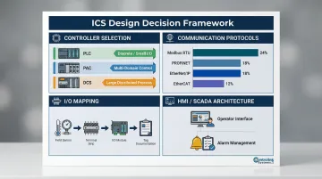
Key design decisions shape everything downstream:
- Controller selection: PLCs handle discrete control with small-to-medium I/O counts well; PACs suit multi-domain applications combining logic, motion, and drives; DCS fits large distributed systems requiring high availability and plant-wide databases
- I/O mapping: Every input and output must be documented with sensor types, signal ranges, and wiring terminations before any code is written
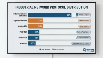
- Communication protocols: PROFINET and EtherNet/IP each hold 18% market share; EtherCAT (12%) dominates high-speed motion applications; Modbus RTU still accounts for 24% of newly installed nodes due to low cost and noise immunity
- HMI/SCADA architecture: Operator interface requirements, alarm management strategies, and data logging specifications must be defined at this stage, not retrofitted later
- Integration points: Connections to existing databases, production systems, and other control equipment need to be mapped early. Controlink Systems navigates these decisions for manufacturing clients, interfacing with SQL databases, PLCs, and multi-axis motion controllers across multiple protocols
Modular design principles break the system into discrete functional modules — motor control, alarm handling, data logging, interlock logic — which makes programming more structured, testing more manageable, and future modifications less risky. A well-designed modular architecture allows individual subsystems to be tested independently before integration.
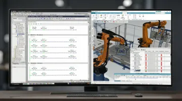
Phase 2: Programming the Control Logic
Programming translates the FRS/PCN into executable control logic. This includes writing ladder logic, function block diagrams, or structured text per IEC 61131-3, configuring I/O, establishing communication links, defining alarm thresholds, and building safety interlocks. The choice of language should match the application: ladder logic for sequential relay-style control, structured text for complex calculations and data manipulation, function block diagrams for modular process control, and sequential function charts for batch processes and state machines.
The IEC 61131-3 standard officially removed Instruction List (IL) in the 2025 Edition 4 release, meaning legacy IL codebases must be migrated to Structured Text or other supported languages to align with modern standards and improve maintainability.
Simulation and bench testing before deployment catch logic errors, misconfigured timers, and communication faults early. Virtual commissioning using digital twin simulations reduces on-site commissioning time by up to 70% and cuts physical rework by 40-50%. Deferring all software verification to the site is one of the most expensive mistakes in ICS projects: it turns commissioning into a debugging exercise instead of a validation process.
Documentation at this stage is a hard requirement:
- I/O lists with current and accurate terminal assignments
- Network diagrams showing communication topology
- Parameter settings including PID gains, setpoints, and alarm limits
- Module descriptions explaining the purpose and logic of each functional block
These documents become the foundation for commissioning procedures and long-term maintenance. Without them, every troubleshooting call starts from scratch, and future modifications risk breaking logic no one fully understands anymore.
Phase 3: Commissioning and Validation
Pre-commissioning activities establish the baseline:
- Applying first power to control panels and verifying no immediate faults
- Confirming communications between cubicles and the control room
- Performing point-to-point checks to verify that field wiring matches the I/O list
- Conducting loop checks to confirm that end devices communicate correctly with the PLC
- Validating safety interlock functions in isolation before system-level testing begins
System-level commissioning operates all equipment under automated control to verify that the plant or machine process responds correctly to every normal operating scenario and every defined fault scenario, using the FRS/PCN as the verification checklist. This phase requires experienced commissioning personnel who can analyze system responses in real time and adjust logic or parameters as needed. Commissioning timelines vary drastically by complexity. Machine-level PLC commissioning may take days to weeks, while complex DCS deployments can require up to six months of dedicated automation testing.
Factory Acceptance Testing (FAT) and Site Acceptance Testing (SAT) serve as formal validation milestones:
- FAT (per IEC 62381:2024): Verifies that hardware and software meet specifications together before the system ships. Defects caught here cost far less to fix than defects found after installation.
- Skipping FAT shifts all problem discovery to the site, where fixes are slower and more expensive. Approximately 80% of factory test failures trace back to incomplete documentation and rushed procedures, not equipment failures. That means most commissioning delays are a direct result of planning decisions made weeks or months earlier.
Key Factors That Affect ICS Design, Programming, and Commissioning
Several variables influence outcomes across all three phases:
Hardware design completeness: Programming cannot be finalized without a complete I/O list and confirmed hardware architecture. Partial designs lead to rework and commissioning delays. Undefined inputs, missing sensor specs, and unresolved wiring questions all surface during commissioning, where changes carry the highest cost.
Communication protocol compatibility: Legacy equipment may run on older protocols such as RS-232 or older Modbus variants that require bridging to modern Ethernet-based systems. Industrial Ethernet accounts for 68% of new nodes, but legacy fieldbuses still retain 24% market share.
Protocol mismatches are a leading cause of integration failures, particularly when modernizing decades-old proprietary systems not designed for interoperability.
Commissioning team involvement timing: Teams involved early in the project can develop test procedures in advance, define mechanical completion sequences, and participate in FAT. Teams brought in late are forced to develop procedures in real time, which extends commissioning significantly and increases the risk of overlooked validation steps.
Environmental and site conditions: Vibration, temperature extremes, electromagnetic interference, and physical distance between field devices and control panels affect hardware selection, cable specifications, and network design. Modbus RTU over RS-485 remains compelling for edge data acquisition because its differential serial driver provides excellent noise immunity in harsh environments and supports long multi-drop cable runs (up to 1200m) without switches.
Safety and regulatory requirements: Industries such as medical device manufacturing, aerospace, and automotive production may require specific validation protocols, documentation standards, or interlock configurations that must be designed into the system from the beginning—not retrofitted during commissioning. Pharmaceutical systems governed by FDA 21 CFR Part 11 and ISPE GAMP 5 require strict traceability matrices linking the FRS to Installation Qualification (IQ), Operational Qualification (OQ), and Performance Qualification (PQ) test protocols.
Common Mistakes and Misconceptions
Three mistakes account for the majority of costly ICS project failures. Recognizing them early prevents schedule overruns and failed commissioning runs.
Treating Programming as an Afterthought
Code development runs in parallel with hardware design — it cannot begin in earnest without a finalized I/O list and communication architecture. Teams that assume code can be written quickly once hardware is built routinely transform a planned six-week commissioning window into a six-month debugging ordeal. It's the most expensive schedule assumption in ICS projects.
Treating Commissioning as a Final Check
Commissioning is a structured verification process, not a walkthrough. Done correctly, it requires:
- Written test procedures prepared before site arrival
- Defined fault scenarios covering expected edge cases
- Formal documentation of results for each tested function
Without these, critical failure modes go untested. Systems that "seemed to work" during informal observation fail under real operating conditions.
Assuming FAT Guarantees a Clean Site Commissioning
A successful Factory Acceptance Test validates hardware and software design — nothing more. Field wiring errors, cable termination faults, and site-specific integration differences don't exist in the factory test environment. Point-to-point checks and loop checks on site remain essential regardless of FAT results. Physical installation always introduces variables that a controlled factory setting cannot replicate.
Conclusion
Design, programming, and commissioning are not isolated activities but a connected lifecycle where quality at each phase depends on the completeness of the phase before it. Shortcuts in any stage propagate as compounding problems—driving schedule overruns, costly rework, and unplanned downtime that could have been caught weeks earlier.
In manufacturing environments where uptime, precision, and system integration are non-negotiable, the ICS lifecycle demands disciplined engineering at every step. The difference between a system that performs reliably on startup and one that requires months of troubleshooting comes down to three things: complete design specifications, programming validated against real-world conditions before deployment, and commissioning that tests every operational scenario—not just the expected ones.
For organizations that need reliable outcomes without deep internal expertise in CNC/DNC communications, shop-floor automation, or multi-protocol integration (Modbus, EtherCAT, Profinet, CAN), partnering with a specialist is often the most direct path. Controlink Systems LLC has worked with manufacturers across the spectrum—from job shops and stamping plants to 3M, Timken, and Oak Ridge National Laboratory—building control and monitoring systems that run continuously in production environments since 1998.
Frequently Asked Questions
What is the difference between FAT and SAT in industrial control system commissioning?
FAT (Factory Acceptance Testing) verifies that hardware and software meet specifications at the vendor's facility before the system ships. SAT (Site Acceptance Testing) is conducted after installation to confirm correct field wiring, proper installation, and basic software function in the actual production environment.
What programming languages are used for PLC-based industrial control systems?
The IEC 61131-3 standard defines five languages—Ladder Logic, Function Block Diagram, Structured Text, Sequential Function Chart, and Instruction List (removed in 2025 Edition 4). Ladder Logic and Structured Text are the most widely used in manufacturing, with Ladder Logic preferred for discrete control and Structured Text for complex calculations and data manipulation.
What communication protocols are commonly used in industrial control systems?
Common protocols include PROFINET and EtherNet/IP (each holding 18% market share), EtherCAT (12%, dominant in high-speed motion), Modbus RTU/TCP, CAN, UDS (ISO 14229 for automotive diagnostics), and Serial (RS-232/RS-485). Protocol selection depends on speed, distance, device compatibility, and integration requirements of the specific application.
Can a new industrial control system be integrated with existing legacy manufacturing equipment?
Integration is possible but requires careful compatibility assessment. Older equipment may use protocols not natively supported by modern PLCs, requiring protocol converters, gateway devices, or custom interface software to bridge the gap. Legacy fieldbuses still account for 24% of newly installed industrial network nodes, making bridging strategies essential for modernization projects.
How long does the commissioning phase typically take for an industrial control system?
Commissioning timelines depend on system complexity. Simple machine-level systems may wrap up in days to weeks, while large DCS or multi-machine automation systems can require weeks or even six months of structured testing, loop checking, and fault scenario validation.
What documents are required before commissioning an industrial control system can begin?
Commissioning requires a completed Functional Requirement Specification or Process Control Narrative, accurate as-built wiring and network diagrams, a finalized I/O list with current terminal assignments, and written test procedures prepared in advance. Without these in place, what should be a structured validation process quickly becomes unguided troubleshooting.