Introduction
Most shop floors still rely on clipboards, manual tally sheets, or verbal reports to track production data. This gap between what's happening on the floor and what management sees creates costly blind spots in quality, output, and uptime. According to recent industry data, 70% of manufacturers still collect shop floor data manually, suffering an average error rate of 1% that compounds across thousands of daily inputs. Manufacturing employees waste over 11 hours per week on "gray work"—the manual, inconsistent efforts required to manage information and analyze performance.
Automating shop floor data collection isn't a single decision—it's a series of them. Results vary widely depending on machine age, communication protocols, software choices, and how well the system fits existing workflows.
Most failed implementations share a common thread: teams underestimate what it takes to bridge modern and legacy equipment, or they pick software before understanding how their machines actually communicate.
This guide walks through the exact steps to automate shop floor data collection, what's required before you start, the variables that determine success, and the mistakes that trip up most implementations.
Key Takeaways
- Automated shop floor data collection replaces manual tracking with real-time, system-generated data from machines, sensors, and networked software
- Success depends on knowing what data you need, how each machine communicates, and which software bridges modern and legacy equipment
- Key variables: machine connectivity type, protocol compatibility, data granularity, and ERP or MES integration depth
- Most failures come from skipping the machine audit, underestimating legacy connectivity, or deploying systems operators won't use
How to Automate Shop Floor Data Collection: Step-by-Step
Step 1: Audit What Data You Need and Where It Currently Lives
List the specific production data points most critical to your operation: cycle times, part counts, machine uptime/downtime, scrap counts, tool wear flags, job status. Identify which of these are currently manual, which are semi-automated, and which are entirely uncaptured.
Map each data point back to its source:
- Machine-generated data: CNC controller output, cycle complete signals, alarm codes
- Sensor-generated data: Temperature, vibration, pressure readings from external sensors
- Operator-reported data: Downtime reason codes, job confirmations, scrap counts
Define success criteria before choosing any hardware or software. For example: "We need cycle time and downtime reason captured per machine in under 5-second latency." Concrete benchmarks like this let you evaluate tools against real operational needs — not vendor marketing.
Step 2: Assess Machine Connectivity and Communication Capabilities
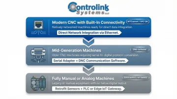
Categorize your machines into three groups:
- Modern CNC with built-in connectivity – Ethernet/MTConnect/OPC-UA support
- Mid-generation machines – RS-232 serial ports requiring DNC communication software
- Fully manual or analog machines – Need external sensors or PLCs for data capture
For each machine, document:
- Available output ports (RS-232, Ethernet, USB)
- Supported protocols (Modbus, Profinet, EtherCAT, CAN)
- Whether the controller outputs real-time data or only logs to local memory
Legacy CNC machines with serial ports are extremely common in job shops. They're not a dead end — they require a DNC software layer to transmit NC programs and capture machine data bidirectionally. Controlink Systems' DNC communication software handles this scenario directly, letting shops connect mixed-age machine fleets without replacing functional equipment.
Step 3: Select and Deploy Data Collection Hardware and Software
Based on your machine connectivity assessment, select the appropriate collection layer for each machine type:
- IoT gateways or edge devices for modern networked machines
- DNC/CNC communication software for serial-connected machines
- Sensor hardware (current transducers, vibration sensors, PLCs) for analog or non-communicating equipment
Install collection nodes or software agents at each machine. The collection method must match each machine's output capability — a one-size-fits-all approach is one of the most common causes of incomplete data coverage on mixed-fleet floors.
Verify that your software can read from and write to SQL databases or your data historian. That connection is what converts raw machine signals into usable production records.
Step 4: Configure Communication Protocols and Integrate with Upstream Systems
Set up the communication protocol stack for each machine group:
- RS-232 connections – Configure baud rate, parity, and handshaking
- Ethernet-connected machines – Set up IP addressing and port mapping
- PLC-linked equipment – Configure Modbus registers or EtherCAT network parameters
Integrate the collected data with your ERP, MES, or SQL database so that job traveler data, work orders, and quality records automatically update without manual entry. Floor activity and business systems stay in sync without manual reconciliation.
Test bidirectional data flow where applicable. For CNC machines, confirm that NC programs can be pushed from the server to the machine (DNC direction) and that cycle complete signals or alarm codes are returned to the server (data collection direction).
Step 5: Validate, Establish Alerts, and Train Operators
Run a parallel validation phase — keep manual data collection running alongside the automated system for 1–2 weeks. Compare outputs to identify discrepancies caused by misconfigured triggers, missed signals, or operator input gaps.
Configure real-time alerts and dashboards for critical metrics:
- Machine-down events
- Scrap threshold breaches
- Cycle time deviations
Without alerts tied to thresholds, collected data sits in a database rather than driving decisions on the floor.
Keep operator interaction minimal and intuitive. If operators must confirm job starts or input downtime reasons, ensure the HMI interface requires only a few taps. Complexity at the operator level is the fastest way to corrupt automated data with skipped entries.
What You Need Before Automating Shop Floor Data Collection
Your automated data collection system is only as good as the groundwork laid before implementation. Undefined data goals and an undocumented machine fleet will produce unreliable data just as reliably as manual entry errors — only faster.
Equipment and Connectivity Requirements
Each machine needs a readable output before any software can collect from it. Document the following for every CNC on your floor before selecting software:
- Communication interface: RS-232 port, Ethernet port, analog sensor tap, or PLC I/O signal
- Controller model and firmware version: Protocol support varies significantly by brand and age
- Machine age and retrofitability: Older controllers may need a hardware adapter or serial converter
Software and Integration Readiness
Confirm your DNC or data collection software can handle both the machines on your floor and the systems upstream. Key questions to answer before committing to a platform:
- Does the software support the protocols your controllers use (serial, Ethernet, Modbus, etc.)?
- Can it write structured data to a database or connect via API to your ERP or MES?
- Has the vendor demonstrated working integrations with your specific controller brands — Fanuc, Siemens, Haas, Mazak?
Operator and Process Readiness
Operator buy-in is often the most overlooked prerequisite. Machinists who don't understand what's being captured — or fear it's surveillance — are a leading source of data gaps and deliberate workarounds.
Before go-live, clarify two things with your team: which data points are fully machine-generated, and which require operator input or confirmation. That distinction shapes both training and system design.
Key Variables That Determine Automated Data Collection Success
Even well-configured automated data collection systems produce inconsistent or misleading results when key variables are poorly controlled. These aren't optional considerations but core design decisions that must be made during planning.
Machine Communication Protocol Compatibility
If your data collection software doesn't natively support the protocol your machine uses — such as RS-232 DNC for legacy CNCs, Modbus for PLCs, or OPC-UA for modern controllers — you'll get no data, corrupted data, or expensive custom middleware.
Mismatched protocols are the single most common cause of "the system works on some machines but not others." Map your protocol requirements before purchasing any software.
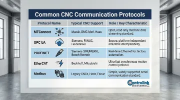
Common CNC Communication Protocols:
| Protocol | Typical CNC Support | Role in CNC Communication |
|---|---|---|
| MTConnect | Modern CNCs (Mazak, Haas NGC); legacy machines via adapters | Open-source, read-only protocol built on XML/HTTP providing standardized semantic vocabulary |
| OPC UA | Siemens SINUMERIK, modern European CNCs | Platform-independent, secure interoperability standard for machine-to-machine communication |
| PROFINET | Siemens, high-performance automation cells | Industrial Ethernet standard offering Real-Time (RT) for 1-10 ms cycle times |
| EtherCAT | Beckhoff, advanced motion control | Ethernet-based fieldbus system optimized for performance and predictability |
| Modbus | Broad legacy and modern support | Simple, widely supported protocol using RS-232, RS-485, and TCP/IP |
Data Granularity and Sampling Rate
Collecting data at too low a frequency — such as end-of-shift summaries — misses short-duration events like micro-stops or tool breakage alarms. Collecting at too high a frequency generates database bloat that slows query performance.
The table below maps common monitoring applications to practical sampling rates so you can match collection frequency to what your use case actually needs.
Recommended Sampling Rates by Application:
| Monitoring Use Case | Recommended Sampling Rate | Protocol Guidance |
|---|---|---|
| Cycle Time / Part Count | 1 Hz (1 sample/second) or Event-Driven | MTConnect sampleRate attribute; OPC UA publishing intervals |
| Temperature Monitoring | 1 Hz to 10 Hz | MTConnect / Modbus (steady-state, low frequency) |
| Spindle Load / Torque | 100 Hz to 2,000 Hz | High-speed adapters; NIST notes CNC applications may require 2000 Hz update rates |
| Vibration / Condition | 50 kHz to 200 kHz | EtherCAT / Dedicated DAQ hardware; requires high sample rates to capture transient faults |
The Nyquist theorem provides a theoretical baseline: to avoid aliasing and accurately capture high-frequency faults (such as bearing defects or gear mesh), the sampling rate must be at least twice the highest frequency of interest, with practical guidelines suggesting 10x for noisy signals.
Integration Depth with ERP or MES
Data collected in an isolated system that doesn't feed work order status, job costing, or quality records back into your ERP creates an information silo that still requires manual reconciliation.
Shops that integrate floor data with ERP systems eliminate double-entry and can measure actual vs. standard cycle times per job: a key input for accurate quoting and scheduling.
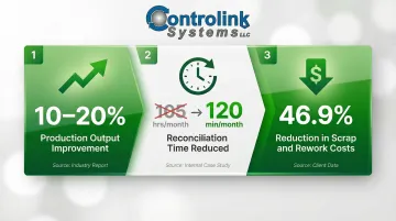
Measurable Improvements from Integration:
- 10% to 20% improvement in production output for manufacturers integrating smart manufacturing initiatives
- Reduction in monthly reconciliation time from 105 hours to just 120 minutes by eliminating manual data entry
- 46.9% reduction in scrap and rework costs by implementing MES with embedded quality management
Operator Compliance Rate
Automated systems that require operator input — such as downtime reason codes or job confirmation — are only as good as the rate at which operators consistently complete those inputs.
Human error accounts for approximately 23% of unplanned downtime in manufacturing. A NIST study found that when designated data-entry schemas don't match the technician's reality, operators frequently select "misc" or "other" to bypass the system, producing unusable data that blocks analytics entirely.
HMI Usability Best Practices:
- Feedback for data entry and control actions must not be greater than two seconds or less than half a second
- Limit input to selections from a list (drop-downs) or use radio buttons when there are eight or fewer options
- Follow ISA-101 standards to reduce clutter and visual chaos on screens
Common Mistakes When Automating Shop Floor Data Collection
Skipping the Machine Connectivity Audit
Jumping straight to software selection without first documenting each machine's communication capability results in purchasing tools that can't interface with half your equipment—the most expensive mistake in the process.
An effective MES deployment must begin with a complete Machine Connectivity Audit (MCA). Assuming machines can be connected via a standard Ethernet cable is a leading cause of stalled deployments.
Treating All Machines the Same
Applying a single collection method (IoT sensors only, for example) across a fleet that includes both network-connected and RS-232 machines leaves legacy CNCs producing no data. A partial system creates false confidence in coverage — gaps in data go unnoticed until bad decisions get made from incomplete reports.
Overcomplicating the Operator Interface
Every required tap or screen a machinist must interact with to log data is a compliance risk. Systems that require more than 2–3 operator actions per job cycle will see declining compliance within weeks of go-live.
Key interface principles to follow:
- Limit required operator actions to 2–3 per job cycle
- Use large, clear touch targets sized for gloved hands
- Display only the fields relevant to the current operation
- Avoid free-text entry wherever a dropdown or scan will do
Ignoring Data Validation at Go-Live
Retiring manual backups before completing a parallel validation phase is a costly shortcut. Configuration errors — wrong trigger events, missed signals, miscalibrated sensors — go undetected and can corrupt weeks of historical data before anyone notices.
When Does Automating Shop Floor Data Collection Make Sense?
Automation is not justified purely by shop size. A 10-machine job shop losing hours per week to manual data entry or running blind on scrap rates has as strong a case for automation as a 200-machine plant. The cost of inaction compounds with every part run.
Signs manual collection is failing:
- Supervisors spend more than 30 minutes per shift reconciling production counts
- Scrap discovered after the fact with no traceable root cause
- Quoting relies on estimated rather than measured cycle times
- Machines sit idle for unknown reasons because no one logged the downtime
The cost of unplanned downtime:
- General manufacturing: $260,000 per hour
- Large US facilities: $532,000 per hour
- Automotive sector: $2.3 million per hour
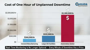
Those numbers apply when something breaks unexpectedly. The case for automation is harder to ignore when your shop has no data to catch problems before they reach that point.
Where full automation may be premature:
- Shops with primarily manual or non-CNC equipment where sensor hardware costs outweigh the output volume
- Facilities without any IT infrastructure to host or connect a data collection system
- Environments where process variability is too high to define standardized data fields yet
In these cases, start with your highest-value machines and expand from there. Phased implementation is a practical path forward, not a compromise.
Frequently Asked Questions
What types of data can be collected automatically from the shop floor?
Automated shop floor data collection captures machine cycle times, part counts, spindle uptime/downtime, alarm codes, NC program execution status, and sensor readings (temperature, vibration, pressure). Simple HMI interfaces can also pull in operator-confirmed events like job starts and scrap counts.
How do older CNC machines with RS-232 ports connect to automated data collection systems?
Legacy CNCs with RS-232 ports connect through DNC software paired with Ethernet-to-serial hubs or wireless edge gateways. These adapters extract cycle data from older machines without requiring hardware replacement, bringing legacy assets into your automated collection system.
What is the difference between manual and automated shop floor data collection?
Manual collection relies on operator-recorded logs that are delayed, error-prone (approximately 1% error rate), and inconsistent between shifts. Automated collection captures machine-generated data in real time with no operator input required for most metrics, eliminating transcription errors and providing immediate visibility into production status.
Can automated shop floor data collection integrate with ERP or MES systems?
Yes — modern systems connect via SQL database connections, APIs, or native connectors. This syncs actual floor data directly to work orders, eliminates double-entry, and gives shops accurate actual vs. standard cycle times for quoting and scheduling.
How long does it take to implement automated shop floor data collection?
A small shop with modern CNCs can go live in days. Mixed-age fleets requiring DNC setup and ERP integration typically take several weeks to a few months, plus a 1–2 week parallel validation phase to confirm data accuracy.
What ROI can manufacturers expect from automating shop floor data collection?
Leesta Industries achieved a 10% reduction in cycle times and 4% gain in OEE by implementing toolpath-level machine monitoring software. Trenton Pressing improved their OEE by nearly 40 percentage points in one year, unlocking capacity that allowed a 50% increase in units shipped while decreasing shifts from two to 1.25.
Conclusion
Automating shop floor data collection works best when it begins with a clear machine connectivity audit, a defined set of target data points, and software matched to the actual protocols present on the floor.
Most failures trace back to skipping the audit phase, underestimating legacy machine complexity, or deploying a system operators can't or won't use consistently. Getting these fundamentals right is what separates a system that drives decisions from one that just collects unused data.
When the foundation is solid, the results follow:
- Eliminates blind spots created by manual tracking
- Reduces unplanned downtime through real-time machine visibility
- Improves quoting accuracy with reliable cycle time and utilization data
- Gives production managers the floor-level insight to act, not just report