Introduction
Force sensors used in manufacturing, testing, and automation are only as trustworthy as their last calibration. Yet many engineers struggle to quantify exactly what "accurate" means once a sensor has been calibrated.
When a production line depends on force measurements to validate product quality — or a test rig must detect defects within a 0.1% tolerance window — a poorly understood accuracy spec can translate directly into scrap, recalls, and unplanned downtime.
This guide defines force sensor accuracy in practical terms, breaks down realistic accuracy ranges by sensor type, and explains what proper calibration actually delivers. Whether you're specifying sensors for end-of-line testing or troubleshooting drift in an existing system, you'll learn how to match sensor performance to your application's actual requirements.
Key Takeaways
- Sensor accuracy varies widely by type: precision load cells hit ±0.02%–±0.5%, industrial sensors ±0.1%–±1%, and force-sensitive resistors only ±5%–±10%
- Calibration corrects sensor output against traceable reference loads, accounting for linearity, hysteresis, repeatability, and zero stability
- Post-calibration accuracy degrades from temperature shifts, overloading, mechanical drift, and strain gauge aging
- The 4:1 rule requires calibration reference standards to be four times more accurate than the sensor being calibrated
- Annual recalibration is standard, but harsh environments and critical applications require more frequent intervals
What Does Accuracy Mean for a Calibrated Force Sensor?
Trueness vs. Precision: Two Distinct Performance Parameters
In measurement technology, "accuracy" is not a single number. The International Vocabulary of Metrology (VIM) 3rd Edition defines it as a qualitative concept describing closeness to the true value — one that cannot be assigned a numerical value directly. Engineers instead evaluate two distinct parameters:
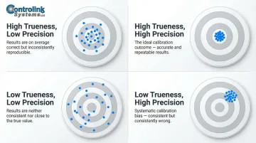
Measurement trueness relates to systematic error. A sensor with high trueness consistently reads close to the real applied force, with minimal bias or offset. Measurement precision describes repeatability under identical conditions—how tightly clustered your readings are when you apply the same force multiple times.
A sensor can be precise but not true (consistently reads 5% high), or true but not precise (readings scatter around the correct average). Calibration addresses trueness directly — correcting systematic offset and slope errors — but precision is an inherent hardware characteristic that calibration cannot improve.
Measurement Uncertainty: Quantifying Doubt
To put a number on measurement quality, the Guide to the Expression of Uncertainty in Measurement (GUM) defines measurement uncertainty as the parameter characterizing the dispersion of values that could reasonably be attributed to the measurand. Uncertainty is expressed as:
- Type A uncertainty: Calculated statistically from repeated measurements
- Type B uncertainty: Estimated from calibration certificates, manufacturer specs, and drift data
For example, if a calibration certificate states an expanded uncertainty of ±0.05% at 95% confidence, you know that the true force value lies within that band 95 times out of 100.
Accuracy Classes: A Standardized Rating System
Force and torque sensors are often rated by accuracy class — a numerical designation (such as Class 0.5 or Class C3) that rolls linearity, hysteresis, temperature drift, and repeatability into a single figure of merit. Two major classification systems apply:
OIML R60 covers legal metrology for industrial weighing. Class C3 sensors are certified for 3,000 verification intervals (commercial weighing), while Class A sensors extend to 50,000+ intervals for laboratory-grade precision.
ISO 376 governs force-proving reference instruments. Class 00 instruments achieve a worst-case expanded uncertainty of 0.08% and serve as primary calibration standards; Class 2 reaches 0.64%, appropriate for secondary transfer standards.
What Calibration Actually Does for Accuracy
Calibration establishes the sensor's actual characteristic curve against traceable reference loads. It corrects or documents the sensor's true output behavior so errors can be quantified and compensated. Without calibration, stated accuracy specs are theoretical manufacturer claims, not verified performance.
Calibration does not improve a sensor's inherent repeatability or reduce its sensitivity to temperature—it simply tells you what the sensor's real behavior is, so you can account for it.
Typical Accuracy Ranges: Calibrated Force Sensors by Type
High-Precision Strain Gauge Load Cells
Used in aerospace, medical devices, and critical manufacturing applications, top-tier strain gauge load cells deliver exceptional performance:
| Sensor Model | Nonlinearity (% FS) | Hysteresis (% FS) | Non-Repeatability (% RO) |
|---|---|---|---|
| Interface 1100 Series | ±0.03% to ±0.06% | ±0.02% to ±0.06% | ±0.01% |
| HBK Z6 (Class C6) | ±0.011% | ±0.008% | Combined error limits apply |
After calibration, these sensors achieve accuracy within ±0.02% to ±0.05% of full scale. That level of precision matters most when traceability to national standards (NIST, PTB) is required and measurement uncertainty must be carefully documented for regulatory or quality submissions.
Standard Industrial Load Cells
For general manufacturing, EOL testing, and process control, standard industrial sensors balance cost and performance:
- Typical accuracy: ±0.1% to ±0.5% of full scale after calibration
- Examples: Mettler-Toledo 0743 (combined error ≤ 0.018% R.C.), Kistler 4579A (accuracy better than 0.2% FSO)
These sensors are rugged and reliable — the right fit for most production environments where tenths-of-a-percent accuracy is enough.
Force-Sensitive Resistors (FSRs)
FSRs are ultra-thin polymer devices used in consumer electronics, robotics, and light-duty detection. Independent benchmarking studies confirm they exhibit hysteresis and drift one to two orders of magnitude greater than strain gauge load cells:
- Typical accuracy: ±5% to ±10% even after calibration
- Hysteresis: Up to 10%
- Long-term drift: <5% per log₁₀(time) over 35 days
FSRs work well for:
- Qualitative touch detection or relative force changes
- Applications where cost and form factor outweigh absolute accuracy
They are not appropriate for critical force measurement, safety testing, or any application requiring traceability to calibration standards.
Accuracy vs. Repeatability: Knowing the Difference
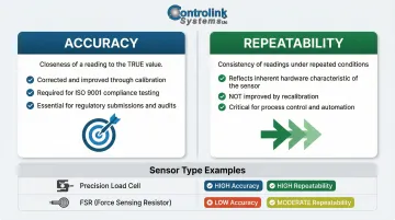
A repeatable but less accurate sensor — like an FSR or low-cost force transducer — can be useful when detecting relative force changes matters more than absolute values. For example, an FSR can reliably detect whether a button press is light or firm, but it cannot tell you the force is 4.7 N versus 5.2 N. Where ISO 9001-compliant production testing or regulatory submissions demand specific force values, only traceable, calibrated load cells qualify.
Key Factors That Affect Force Sensor Accuracy
Linearity and Hysteresis
Non-linearity is the maximum deviation of the actual calibration curve from a straight line between zero and full-scale load, expressed as a percentage of rated output. If your sensor has ±0.05% nonlinearity and you're measuring across its full range, expect up to 0.05% error purely from curve deviation—even after calibration.
Hysteresis is the difference in sensor output for the same applied load when approached from increasing vs. decreasing directions. Typically measured at 50% of rated output, hysteresis runs ±0.02% to ±0.06% for precision load cells. Fast loading cycles can mask or amplify this error, so standardize your loading profile during both calibration and field use.
Zero Offset, Repeatability, and Temperature Effects
Zero offset (zero balance) is the sensor output at no load. Over time, this offset drifts due to aging, temperature changes, and mechanical stress. Calibration corrects the initial offset, but monitoring zero drift between calibrations is critical, particularly in automated test systems. A drifting zero can compound across thousands of measurements and is easy to miss without continuous monitoring.
Non-repeatability sets a hard ceiling on measurement consistency, regardless of calibration quality. It's the maximum output difference between identical loads applied under identical conditions. High-precision load cells achieve non-repeatability of ±0.01% RO; standard sensors range from ±0.02% to ±0.05%.
Temperature effects are often the largest source of accuracy degradation in real-world environments. Both zero output and sensitivity shift with temperature:
- Temperature Coefficient of Zero (TCO): Typical values are ±0.0015% RO/°C
- Temperature Coefficient of Span (TCS): Typical values range from ±0.0015% to ±0.008% RO/°C
If your shop floor temperature swings by 10°C during a production shift, uncorrected temperature effects can introduce ±0.15% error even in a recently calibrated sensor. Process monitoring systems that track environmental conditions alongside force data can flag these deviations before scrap accumulates. Controlink Systems builds exactly this type of shop-floor traceability into their process monitoring solutions, triggering recalibration alerts when temperature-related drift is detected.
How Calibration Improves Accuracy: Procedures and the 4:1 Rule
Three Calibration Procedures: When to Use Each
Each calibration procedure suits a different application. The table below summarizes when to use each:
| Procedure | What It Corrects | Best For |
|---|---|---|
| One-point | Zero offset only | Sensors used at a single fixed load — e.g., a go/no-go fixture at 500 N |
| Two-point | Zero offset + slope (sensitivity) | Linear sensors used across their full range — e.g., web tension from 0 to 1,000 N |
| Multi-point | Full calibration curve (non-linearity, hysteresis, repeatability) | Critical applications requiring rigorously documented measurement uncertainty |
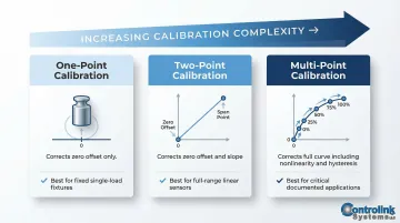
Multi-point calibration typically uses five points (0%, 20%, 40%, 60%, 80%, and 100% of range) in both increasing and decreasing directions. ISO 376 requires a minimum of eight force steps distributed uniformly over the range for the highest-stakes applications.
The 4:1 Test Accuracy Ratio (TAR) Rule
The 4:1 rule states that the reference standard or calibration machine used to calibrate a force sensor must have an uncertainty at least four times smaller than the tolerance of the sensor being calibrated. For example, to calibrate a sensor with a specified tolerance of ±0.2% FS, your reference standard must have uncertainty of ±0.05% or better.
An inadequately precise reference standard doesn't improve real-world accuracy — it creates false confidence. ILAC G8:09/2019 goes further, requiring formal decision rules and guard bands to control acceptance risk when tolerances are tight.
System Calibration vs. Sensor-Only Calibration
Calibrating the sensor alone does not account for errors introduced by the signal conditioner, amplifier, cabling, and connectors. System calibration (sensor + amplifier + cable) provides a single verified calibration curve for the complete measurement chain and is strongly recommended for production and EOL test environments.
If a force transducer is subsequently used with a different indicator than the one it was calibrated with, EURAMET cg-4 requires the deviation between the two indicators to be determined and its uncertainty included in the final uncertainty budget.
How Often Should You Recalibrate Force Sensors?
Standard Recalibration Intervals
Annual recalibration is the general industry baseline for force sensors in normal operating conditions. However, ISO/IEC 17025 does not mandate fixed calibration intervals—determining appropriate intervals is the responsibility of the user and must be based on a sound risk assessment.
Sensors used in critical applications, harsh environments, or high-cycle applications (repeated overloads, vibration, wide temperature swings) may require more frequent recalibration. Factors influencing interval selection include:
- Frequency of device use
- Environmental conditions (temperature, humidity, contamination)
- Accuracy requirements and tolerance margins
- Historical stability data from previous calibrations
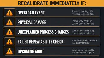
Event-Triggered Recalibration
Scheduled intervals aren't the whole story. Certain events should trigger immediate recalibration regardless of where you are in the cycle:
- Known or suspected overload events (forces exceeding 150% of rated capacity)
- Visible physical damage to the sensor body, cable, or connector
- Unexplained changes in process output or increased scrap rates
- Failed repeatability checks during routine verification
- Upcoming audits requiring documented traceability
In manufacturing environments, linking sensor health checks to process monitoring software lets teams act on early warning signs rather than waiting for a scheduled date. Controlink Systems' process monitoring software continuously tracks measurement data against baseline values and maintains timestamped records for shop-floor traceability — giving engineers a documented trail when audit time comes and a faster path to identifying which sensor triggered a scrap event.
Frequently Asked Questions
How accurate is a force sensor?
Accuracy depends on sensor type and calibration status. Calibrated precision strain gauge load cells achieve ±0.02% to ±0.5% of rated output, standard industrial sensors range from ±0.1% to ±1%, and force-sensitive resistors typically achieve only ±5% to ±10%. Calibration against traceable standards is what closes the gap between rated and actual accuracy.
What is the 4:1 rule of calibration?
The 4:1 Test Accuracy Ratio (TAR) rule requires the calibration reference standard to be at least four times more accurate than the device under calibration. This ensures the calibration process itself does not introduce unacceptable uncertainty into the sensor's verified accuracy.
How much does a sensor recalibration cost?
Force sensor recalibration costs typically range from $150 to $800 depending on sensor capacity, calibration type (single-point vs. multi-point), and whether ISO/IEC 17025 accreditation is required. System calibration covering the sensor, amplifier, and cable costs more but gives more reliable results for production environments.
How often should force sensors be recalibrated?
Annual recalibration is the standard baseline for normal operating conditions. Critical applications, harsh environments, or suspected overload events warrant more frequent intervals — and event-triggered protocols based on zero shifts or fixture changes are often more reliable than fixed annual schedules.
What is the difference between accuracy and repeatability in force sensors?
Accuracy describes how close a measurement is to the true value; repeatability describes how consistently the sensor returns the same reading under identical conditions. A sensor can be highly repeatable but still inaccurate due to systematic offset. Calibration addresses trueness, while repeatability is an inherent sensor characteristic.
What factors most commonly cause force sensor accuracy to degrade over time?
Mechanical drift and strain gauge aging top the list, followed by zero offset drift from temperature cycling, overload events that permanently deform the flexure, and connector or cable degradation in the signal chain. Regular recalibration and environmental monitoring catch these issues before they impact production quality.