Introduction
RS-232 is embedded in industrial equipment that runs factories daily. Walk into any CNC machine shop, and you'll find it connecting CNC machines, PLCs, barcode scanners, scientific instruments, and legacy test systems throughout the facility.
RS-232 is one of those protocols that technicians and engineers deal with regularly but rarely fully understand. That gap leads to misconfigured communication settings, wiring confusion between DTE and DCE devices, and unexplained connection failures that cost real downtime.
When a CNC machine won't accept a program file or a PLC refuses to respond to configuration commands, the root cause is often a mismatched baud rate, incorrect flow control setting, or the wrong cable type.
This guide breaks down how RS-232 actually works — covering its electrical behavior, data structure, and connector roles, along with why it remains the go-to protocol in many manufacturing environments.
Key Takeaways
- RS-232 is an asynchronous serial standard defined by the EIA for connecting data terminal equipment (DTE) to data communication equipment (DCE)
- Inverted voltage logic: −3V to −15V = logic 1 (mark); +3V to +15V = logic 0 (space)
- Each frame carries a start bit, data bits, an optional parity bit, and stop bits — transmitted one bit at a time
- Point-to-point only: one transmitter to one receiver, with a practical cable run of up to 50 feet at standard speeds
- Introduced in 1960, RS-232 still runs CNC machines and industrial controllers thanks to its simplicity and reliability
What Is RS-232?
RS-232 is a hardware and protocol standard for asynchronous serial communication, originally established by the Electronic Industries Association (EIA) to standardize how a DTE (such as a computer or terminal) communicates with a DCE (such as a modem or peripheral). "RS" stands for Recommended Standard, and the full designation is EIA/TIA-232.
Why RS-232 Exists
Before this standard, connecting different manufacturers' serial devices required custom wiring and configurations for every pairing. RS-232 solved this by specifying:
- Voltage levels for logic high and low states
- Connector types and pin assignments
- Signal definitions for control and data lines
- Timing behavior for synchronization
This allowed equipment from different manufacturers to communicate without custom wiring for every pairing.
What RS-232 Is Not
RS-232 is not a networking protocol like Ethernet, nor a software protocol like Modbus. It is a physical and electrical interface standard — it defines how signals travel over a wire, not how data is interpreted by the application layer. This distinction matters when troubleshooting communication failures.
Continued Relevance
Despite being introduced in 1960 and updated through revision F in 1997, RS-232 remains in active use. The global serial device server market was valued at $327.7 million in 2025 and is projected to reach $491.9 million by 2034, driven by the need for network connectivity of legacy serial devices. RS-232's simplicity, low implementation cost, and deep hardware support in legacy equipment make it difficult to displace.
Common Connector Formats
The DB-25 (25-pin) was defined in early revisions, while the DB-9 (9-pin) became the practical standard for most PC and industrial applications. RS-232 does not define character encoding, bit framing, or application-layer protocol. Those are determined by the devices and software using the interface — which is why understanding the physical layer is only the first step.
How Does RS-232 Work?
RS-232 operates through a defined sequence of electrical events. A sender and receiver must agree on the same parameters before communication begins, and data moves one bit at a time across a shared serial line.
Initiation
RS-232 communication begins when both devices are configured with matching parameters:
- Baud rate (bits per second)
- Number of data bits (typically 7 or 8)
- Parity type (even, odd, or none)
- Number of stop bits (1 or 2)
These settings must be manually matched on both ends — there is no auto-negotiation in RS-232.
The TX line idles in a high (mark) state at negative voltage (e.g., −12V) when no data is being sent. To initiate a transmission, the sender pulls the TX line low (to a positive voltage), producing the start bit — this signals the receiver that a data frame is about to begin.
Core Operation
After the start bit, the sender transmits the data bits (typically 8), beginning with the least significant bit (LSB). An optional parity bit follows for basic error detection, and a stop bit closes the frame by returning the line to its idle (high/mark) state.
Inverted Voltage Logic:
- Logic 1 (mark): −3V to −15V
- Logic 0 (space): +3V to +15V
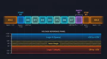
This is the opposite of what engineers used to TTL logic often expect. The receiver recognizes voltages between 3V and 15V as logic 0, and voltages between −3V and −15V as logic 1, providing a 2V minimum noise margin.
Data can only travel from the sender's TX pin to the recipient's RX pin. Bi-directional communication requires two separate signal wires (TX and RX) — one for each direction.
Parity Checking:
- Even parity: Total number of logic-high bits in the frame, including the parity bit, is always even
- Odd parity: Total number is always odd
- If the count doesn't match at the receiver, a transmission error is flagged
Flow Control: RTS, CTS, and XON/XOFF
Hardware handshaking signals — specifically RTS (Request to Send) and CTS (Clear to Send) — act as a traffic management layer. When a DTE asserts RTS, it signals the DCE that it is ready to transmit; the DCE responds with CTS to grant permission.
In CNC and DNC setups, flow control typically falls into one of three configurations:
- Hardware handshaking — RTS/CTS lines actively coordinate transmission between devices
- Software flow control — XON/XOFF characters signal when to pause or resume data
- Loopback — RTS/CTS lines are jumpered together, bypassing handshaking entirely
Mismatched flow control settings are one of the most common causes of RS-232 communication failure in shop-floor environments — and the first thing to verify when a CNC connection drops unexpectedly.
What a Completed RS-232 Frame Delivers
RS-232 produces a reliable, bit-accurate, point-to-point data stream that the receiving device reconstructs byte-by-byte. The stop bit marks the end of each frame and resets the line to idle, letting the receiver cleanly detect the next start bit in a continuous stream.
When baud rate, data bits, parity, and stop bits are all aligned, the protocol transfers G-code programs, machine parameters, and control signals with consistent accuracy — even across the electrically noisy environments typical of a machining floor.
RS-232 Connector and Signal Lines
DB-25 vs. DB-9
Two main connector types exist:
- DB-25 (25-pin): Originally specified by the RS-232 standard to accommodate all defined signals
- DB-9 (9-pin): Became the de facto standard for personal computers and most industrial equipment because most applications only use a subset of the defined signals
By convention, DTE devices use male connectors and DCE devices use female — though real-world installations frequently differ.
Key Signal Lines on DB-9
| Pin | Signal | Function |
|---|---|---|
| 2 | TxD | Transmitted Data |
| 3 | RxD | Received Data |
| 4 | DTR | Data Terminal Ready |
| 5 | GND | Signal Ground |
| 6 | DSR | Data Set Ready |
| 7 | RTS | Request to Send |
| 8 | CTS | Clear to Send |
| 9 | RI | Ring Indicator |
DTE vs. DCE and Null-Modem Cables
In a DTE-to-DCE connection, a straight-through cable works. Connecting two DTEs (such as a PC to a CNC control) requires a null-modem cable that crosses the TX and RX lines.
Practical Wiring Configurations
3-wire connection (TxD, RxD, GND):
- Simple unidirectional or bidirectional data
- No flow control
5-wire connection:
- Adds RTS/CTS for hardware flow control
- Common in CNC machine connections
Start with a 3-wire setup when flow control isn't needed; step up to 5-wire when the CNC control or DNC software requires handshaking to manage data pacing.
Where RS-232 Is Used in Industry
RS-232 fits into manufacturing and industrial workflows at the machine-level interface layer: the point where individual pieces of equipment exchange data with a host computer, controller, or automation system.
Optimal Environments
RS-232 performs best in:
- Electrically noisy factory floors where its relatively high voltage swing (±12V) provides better noise immunity than lower-voltage interfaces
- Short-range, dedicated connections between two devices (up to 50 feet)
- Legacy equipment environments where replacing hardware is impractical
Specific Industrial Applications
- CNC machine tools: Upload and download G-code programs between controller and host
- PLC configuration and monitoring: Siemens S7-1200 controllers support RS-232 modules for serial communication
- Barcode scanners and serial printers: Industrial scanners like the Honeywell HF811 offer RS-232 interfaces
- CMM and metrology devices: Test and measurement instruments in quality labs
- Variable-frequency drives: Configuration and status monitoring on older units
- Scientific instruments: Laboratory equipment in research environments
DNC (Distributed Numerical Control) Systems
DNC remains one of the most common RS-232 applications in active use today. In DNC systems, a computer sends machining programs directly to CNC controllers over an RS-232 serial link. Modern DNC systems work essentially the same way as the original DPRNT command, which embedded commands in G-code to send data over RS-232.
DNC software — including solutions Controlink Systems LLC builds for CNC machine shops — depends on correctly configured RS-232 connections. Machinists receive the latest engineering-approved programs, which directly reduces scrap and improves shop-floor efficiency.
Industry-Specific Usage
Automotive and aerospace manufacturing:
- Older CNC and CMM equipment
- FANUC Series 30i-B Plus controllers include RS-232 Reader/Puncher Interface
Medical device manufacturing and research labs:
- Legacy instrumentation
- Mitutoyo QV Active systems use RS-232C communication for medical component reports
Repair centers and stamping plants:
- Configuration interface for older variable-frequency drives and servo systems
Conclusion
RS-232 is a point-to-point, asynchronous serial protocol that transmits data one bit at a time in structured frames. Its inverted voltage logic, defined connector types, and handshaking signals were all built for one purpose: reliable, predictable serial communication between two devices.
Engineers and technicians who understand the fundamentals can configure equipment correctly and diagnose faults without guesswork. The key concepts to carry forward:
- Frame structure — how start bits, data bits, parity, and stop bits define each transmission
- Voltage behavior — why the logic is inverted and what valid signal levels look like
- DTE/DCE roles — which device drives which line, and why it matters for wiring
- Null-modem requirements — when and how to cross signals for direct device-to-device connections
That knowledge also informs protocol selection. RS-232 works well for short-range, point-to-point links — but for multi-drop networks or longer cable runs, RS-485 is the more practical choice.
Frequently Asked Questions
What is an RS-232 port and what is it used for?
An RS-232 port is a physical serial interface connector (typically DB-9 or DB-25) used to connect two devices for point-to-point serial data exchange. It's commonly found on CNC machines, PLCs, computers, and instruments for configuration, programming, and data transfer.
Is RS-232 still used today?
Yes, RS-232 remains widely active in industrial settings, particularly in CNC machine tools, scientific instruments, PLCs, and DNC systems. Its simplicity, reliability, and long installed base make replacement impractical in most manufacturing environments.
Is RS-232 a serial interface and is it synchronous or asynchronous?
RS-232 is a serial interface (data transmitted one bit at a time) and is fundamentally asynchronous, meaning there is no shared clock signal. Instead, framing is maintained through start and stop bits with both devices configured to the same baud rate.
What is the difference between RS-232 and RS-485 serial interfaces?
RS-232 is single-ended and point-to-point, limited to roughly 50 feet at standard speeds (per TI's RS-232 application note). RS-485 uses differential signaling, supports multi-drop networks of 32 or more devices, and operates reliably over distances up to 4,000 feet (per TI's RS-485 application note). That makes RS-485 the better choice for longer-distance or multi-device industrial networks.
Is RS-232 the same as Modbus?
No. RS-232 and Modbus operate at different layers: RS-232 is a physical interface standard that defines how electrical signals travel over a wire, while Modbus is an application-layer communication protocol that defines how data is structured and interpreted. Modbus can run on top of an RS-232 physical connection.
How is RS-232 used in embedded systems and microcontrollers?
Many microcontrollers include a built-in UART that generates TTL-level serial signals. To connect to RS-232 devices, a level-shifting IC (such as the MAX232) is used to convert between the microcontroller's 3.3V or 5V logic and RS-232's ±12V signal levels.