Introduction
Modern vehicles and industrial machines rely on dozens—sometimes hundreds—of electronic control units (ECUs) exchanging sensor readings, commands, and fault codes in real time. Many engineers face a common challenge: how do you enable reliable, deterministic communication between all these devices without overwhelming the system with wiring or creating a single point of failure?
The answer is CAN bus. According to ISO 11898-1:2024, the Controller Area Network (CAN) is a multi-master, message-based serial communication protocol designed to allow electronic control units and devices to exchange data without a central host computer. With more than 2 billion CAN nodes deployed annually across automotive, industrial, and medical sectors, CAN remains the backbone of distributed real-time control.
This guide is written for engineers, technicians, and systems integrators in automotive, industrial automation, and manufacturing. It covers CAN's arbitration rules, frame structure, error handling, and version differences—everything you need for reliable integration and faster troubleshooting.
Whether you're diagnosing a faulty ECU or wiring a new sensor into a production line, this guide gives you the operational detail to do it right.
Key Takeaways
- CAN bus is a serial protocol developed by Bosch in 1983 — ECUs share a two-wire network with no master controller required
- Uses priority-based arbitration where the highest-priority message always wins access without data loss
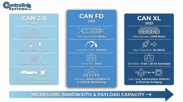
- Three major versions exist: CAN 2.0 (Classical), CAN FD (up to 8 Mbit/s), and CAN XL (up to 20 Mbit/s with 2,048-byte frames)
- Deployed across automotive systems (70–150+ ECUs per vehicle), industrial robotics, and medical devices
- Remains the go-to choice in 2026 for noise immunity, deterministic timing, and a mature tooling ecosystem
What Is the CAN Bus Protocol?
CAN bus is a broadcast-based, half-duplex serial communication standard governed by ISO 11898 that enables distributed real-time control between multiple nodes on a shared bus. All devices connect via two wires—CAN-H and CAN-L—using differential signaling to achieve exceptional noise immunity.
Any device (node) on the network can send and receive messages. Each message carries a priority ID rather than a device address, so all nodes receive all messages and decide whether to act on them. This content-based addressing allows multiple subsystems to share the same sensor data at once, without duplicating wiring.
CAN's design sets it apart from similar protocols used in industrial settings:
- vs. RS-485: CAN is multi-master with built-in arbitration; RS-485 is typically point-to-point or master/slave
- vs. Ethernet: CAN is designed for deterministic, real-time control in electrically noisy environments, not high-bandwidth data transfer
How Differential Signaling Works
CAN-H and CAN-L carry opposing voltage levels, and the difference between them encodes each bit state:
| Bit State | CAN-H | CAN-L | Differential Voltage |
|---|---|---|---|
| Dominant (0) | ~+3.5 V | ~+1.5 V | +2.0 V |
| Recessive (1) | +2.5 V | +2.5 V | 0 V |
Because the receiver reads the difference between the two lines rather than absolute voltage, electrical noise that hits both wires equally gets canceled out. This is what gives CAN its strong immunity to electromagnetic interference in automotive and industrial environments.
How CAN Bus Communication Works
CAN bus communication follows a defined sequence without any central coordinator. A node prepares a message frame, waits for the bus to go idle, broadcasts the frame, and other nodes receive and filter it by ID — the transmitting node then receives an acknowledgment confirming delivery.
Understanding how each step works helps explain why CAN is so reliable in safety-critical environments.
Step 1: Arbitration
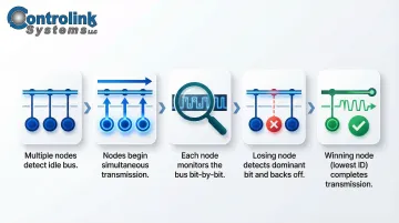
When two or more nodes attempt to transmit simultaneously, CAN resolves the conflict through non-destructive bitwise arbitration:
- Each node monitors the bus as it sends its message ID bit by bit
- If a node transmitting a recessive bit (1) detects a dominant bit (0) on the bus, it knows it has lost priority
- The losing node immediately stops transmitting without disrupting the winner
- The lower the numeric ID, the higher the priority
- The winning node continues without any loss of data
This mechanism ensures the highest-priority message always gains bus access without collision-resolution delays. Once arbitration resolves, the winning node moves directly into frame transmission.
Step 2: Frame Transmission
A standard CAN 2.0 data frame includes these fields:
| Frame Field | Size | Function |
|---|---|---|
| Start of Frame (SOF) | 1 bit | Marks frame start and synchronizes nodes |
| Identifier | 11 or 29 bits | Message ID and priority level |
| Control Field (DLC) | 6 bits | Data Length Code specifying payload size |
| Data Field | 0–8 bytes | Application payload |
| CRC Field | 16 bits | Error detection sequence |
| ACK Field | 2 bits | Acknowledgment slot for receivers |
| End of Frame (EOF) | 7 bits | Seven recessive bits marking frame end |
The identifier serves dual purposes: it defines what the message contains (for example, engine temperature or wheel speed) and determines its bus priority. With the frame on the bus, acknowledgment and error handling take over immediately.
Step 3: Acknowledgment and Error Handling
Any node that successfully receives a valid frame pulls the ACK slot dominant to confirm receipt. If the transmitter detects no acknowledgment, it automatically retransmits. Repeated failures feed into CAN's error-counting system, which tracks node health across the entire network.
Built-in error confinement:
CAN uses a Transmit Error Counter (TEC) and Receive Error Counter (REC) to isolate failing nodes automatically:
- Error-active state: Normal operation — the node participates fully and can send active error flags to signal problems
- Error-passive state: TEC or REC reaches 128 — the node stays on the network but can only send passive (non-disruptive) error flags
- Bus-off state: TEC reaches 256 — the node disconnects from the network entirely and must detect 128 consecutive bus-idle sequences before rejoining
This graduated approach means a single defective node degrades gracefully rather than taking down the entire network.
CAN Bus Versions: CAN 2.0, CAN FD, and CAN XL
Classical CAN (CAN 2.0)
The original standard includes:
- CAN 2.0A: 11-bit identifier
- CAN 2.0B: 29-bit identifier (extended frame format)
- Maximum payload: 8 bytes per frame
- Maximum baud rate: 1 Mbit/s
Classical CAN remains the most widely deployed version and serves as the foundation for higher-layer protocols like SAE J1939 (trucks), CANopen (industrial automation), and DeviceNet (factory automation).
CAN FD (Flexible Data-Rate)
Released by Bosch in 2012 and standardized in ISO 11898-1:2015, CAN FD addresses bandwidth limitations:
- Two-phase bit rate: Lower rate (up to 1 Mbit/s) during arbitration for stability, higher rate (up to 8 Mbit/s) during data phase
- Expanded payload: 64 bytes per frame (vs. 8 bytes in Classical CAN)
- 8x frame reduction: Cuts frame counts for large data transfers by up to 8x
For example, transmitting a 1 MB firmware file over Classical CAN requires over 131,000 frames. With CAN FD's 64-byte payload, the same file requires only ~16,384 frames, slashing OTA update and ECU flashing times by 4x to 8x.
CAN XL (The Newest Version)
Specified in ISO 11898-1:2024 as part of CiA 610-1, CAN XL bridges the gap between CAN FD and Automotive Ethernet:
- Payloads: 1 to 2,048 bytes per frame
- Data rates: Up to 20 Mbit/s in FAST mode
- Backward compatibility: CAN XL controllers can coexist with CAN FD and Classical CAN in mixed networks
CAN XL can encapsulate complete Ethernet frames or IP packets, extending CAN's viability into bandwidth-intensive applications while preserving its arbitration advantages.
Backward Compatibility Considerations
CAN FD devices can coexist on a CAN 2.0 network, but Classical CAN 2.0 nodes cannot interpret CAN FD or CAN XL frames. If a Classical CAN node observes a CAN FD frame, it misinterprets the format as an error and generates an active error frame that destroys the FD traffic.
Network designers have two options to address this:
- Hardware gateways: Physically isolate Classical CAN nodes from FD/XL traffic
- Protocol Exception State: Configure legacy nodes to detect the FD Format (FDF) bit, stop decoding, and wait for bus idle — preventing error storms without a gateway
Higher-Layer Protocols Built on CAN
ISO 11898 defines only the physical and data-link layers. Industries have developed application-layer protocols on top:
| Protocol | Governing Body | Primary Use | Key Features |
|---|---|---|---|
| SAE J1939 | SAE International | Heavy-duty vehicles | 29-bit identifiers for Parameter Group Numbers (PGNs) |
| CANopen | CiA | Industrial automation/robotics | Process Data Objects (PDOs) and Service Data Objects (SDOs) |
| UDS (ISO 14229) | ISO | Automotive diagnostics | Unified Diagnostic Services for ECU control and flashing |
| DeviceNet | ODVA | Factory automation | Combines CAN with Common Industrial Protocol (CIP) |
| NMEA 2000 | NMEA | Marine electronics | Plug-and-play vessel systems (GPS, radar, engine monitoring) |
Where CAN Bus Is Applied
Automotive Applications
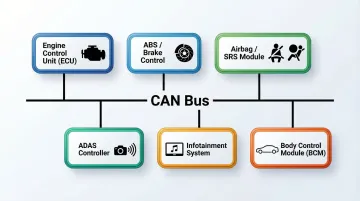
Modern vehicles contain up to 70 ECUs for ADAS alone, and over 150 ECUs for Level 4 autonomous vehicles. CAN bus allows these subsystems to share sensor data without duplicating wiring:
Typical automotive CAN applications:
- Engine control and transmission
- ABS and stability control
- Airbag deployment systems
- Power steering and ADAS
- Infotainment and climate control
This reduces vehicle weight and cost while enabling software-defined features like auto start/stop, collision avoidance, and adaptive cruise control.
Industrial and Manufacturing Applications
CAN's tolerance for electrical noise from motors and actuators makes it ideal for:
- Robotics and CNC machines
- 3D printers and additive manufacturing
- Agricultural equipment (ISO 11783/ISOBUS)
- Factory automation systems
In shop-floor automation and EOL testing environments, CAN typically runs alongside Modbus, Profinet, and EtherCAT — with each protocol handling the tasks it's best suited for rather than one replacing the others.
Cross-Industry Proliferation
That same noise immunity and timing precision that works in factory environments extends well beyond manufacturing. CAN's deterministic timing and fault tolerance have driven adoption across:
- Medical devices: Surgical robots, dialysis machines, advanced prosthetics
- Aerospace: NASA and ESA spacecraft motor controllers and satellite systems
- Marine: NMEA 2000 networks for vessel navigation and engine monitoring
Recurring vs. Condition-Based Usage
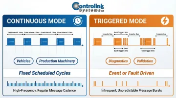
Continuous mode: Nodes broadcast on fixed, scheduled cycles — typical in vehicles and production machinery where real-time data must flow without interruption.
Triggered mode: Messages fire only when a specific test sequence or fault condition occurs — common in diagnostic and validation environments where bus load needs to stay low between events.
Choosing the wrong mode can result in either bus overload or missed fault events — so identifying the usage pattern early shapes every other design decision, from baud rate selection to message priority assignment.
Common Misconceptions and Limitations of CAN Bus
"CAN Bus Is Only for Automotive"
CAN was developed for vehicles, but it's now a standard fieldbus across industrial robotics, medical devices, aerospace, and 3D printing. The same ISO 11898 standards and arbitration rules apply regardless of industry.
"CAN Bus Is Inherently Secure"
CAN has no built-in encryption or authentication. All nodes receive all messages, and a compromised or spoofed node can inject frames that other nodes cannot distinguish from legitimate traffic.
Security must be implemented at the application layer or via supplementary protocols like AUTOSAR SecOC (Secure Onboard Communication), which appends a Message Authentication Code (MAC) and Freshness Value to payloads.
"CAN Bus" vs. "J1939" or "CANopen"
Teams often say they "use CAN" when they actually use J1939 or CANopen. CAN defines only the physical and data-link layers. Protocols like J1939, CANopen, and UDS sit on top of that foundation, specifying message formats, device profiles, and network management rules.
When CAN Bus May Not Be the Right Choice
Not every application is a good fit for CAN. Consider alternatives in these scenarios:
- High-throughput applications — HD video, large software packages, or raw LiDAR data exceed CAN's bandwidth ceiling. Compressed 1080p video requires ~5 Mbit/s; Classical CAN maxes out at 1 Mbit/s. Automotive Ethernet handles this workload better.
- Simple sensor networks — Low-cost networks with no real-time requirements don't need CAN's overhead. LIN bus or IO-Link are more efficient choices.
Don't choose CAN by default for new designs. Evaluate whether CAN FD or an Ethernet-based alternative better matches your throughput and latency requirements.
Frequently Asked Questions
How does the CAN bus protocol work?
All nodes connect to a shared two-wire bus. Each node broadcasts messages identified by a priority ID rather than an address. A lossless bitwise arbitration mechanism ensures the highest-priority message wins access to the bus without data loss.
What is the CAN protocol used for?
CAN coordinates ECUs in automobiles (engine, ABS, airbags, ADAS), industrial automation (robotics, CNC, process monitoring), and diagnostic systems: wherever real-time, noise-tolerant communication between multiple embedded devices is required.
What protocol do cars use?
Modern vehicles primarily use CAN bus (ISO 11898) as the backbone network. It typically runs alongside LIN bus for lower-priority subsystems, FlexRay for safety-critical timing, and increasingly Automotive Ethernet for high-bandwidth needs like cameras and radar.
Is the CAN protocol still relevant?
Yes. CAN remains highly relevant in 2026 due to its noise immunity, deterministic behavior, and vast installed base. The automotive CAN transceiver market is projected to reach $2.0 billion by 2025, growing at 8% annually, with CAN XL extending its viability toward Ethernet-level bandwidth.
Is CANopen used in automotive?
CANopen is primarily used in industrial automation (motion control, robotics, elevator systems) rather than passenger vehicles. The automotive equivalent is SAE J1939 (for trucks and buses) or OEM-specific protocols. CANopen and automotive CAN share the same physical layer but different application-layer definitions.
What is an example of the CAN protocol in automotive?
When a driver presses the brake pedal, the ABS control unit broadcasts a wheel-speed message over the CAN bus. The engine control unit, stability control module, and dashboard simultaneously receive this message and each responds according to its own programmed logic—no central controller orchestrates this exchange.